

Variations for Synthesizing Zero Platinum Group Metal Catalyst Systems
a metal catalyst and platinum group technology, applied in the field of catalyst systems, can solve problems such as driving up the cost of catalysts
- Summary
- Abstract
- Description
- Claims
- Application Information
AI Technical Summary
Benefits of technology
Problems solved by technology
Method used
Image

Examples
example # 1
Example #1
Co—Precipitation Method for ZPGM Cu—Mn Spinel Catalyst Systems
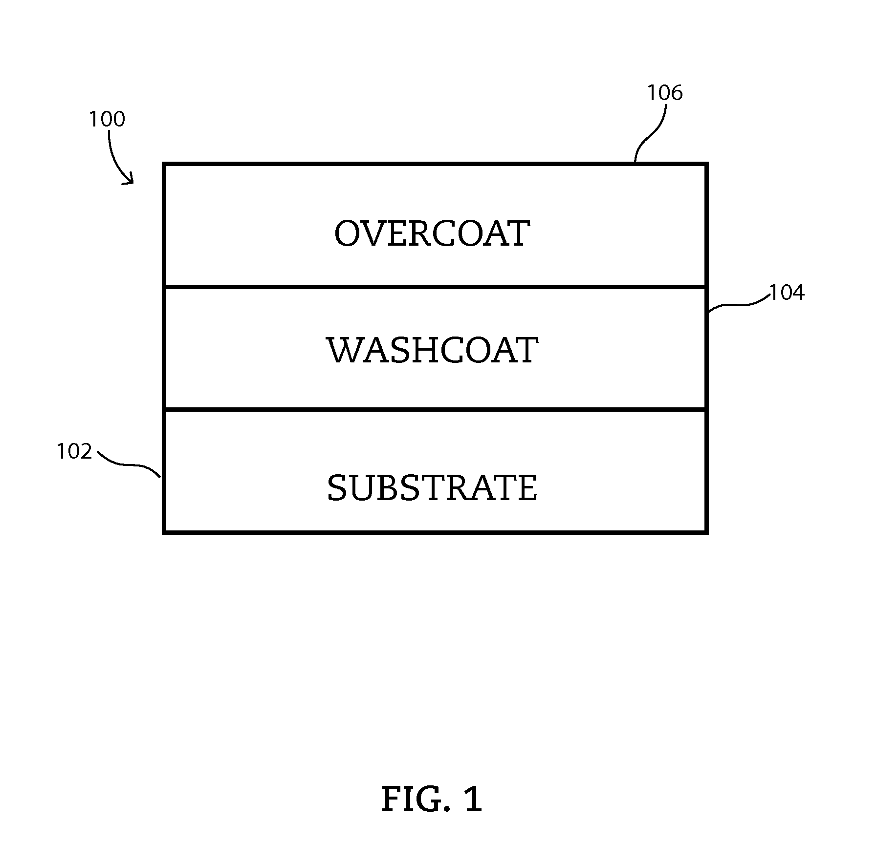
[0058]Example #1 shows ZPGM Cu—Mn powder catalyst of the present disclosure which may be synthesized by co-precipitation method and may include precipitating of Cu—Mn stoichiometric spinels on one or more carrier material oxides.
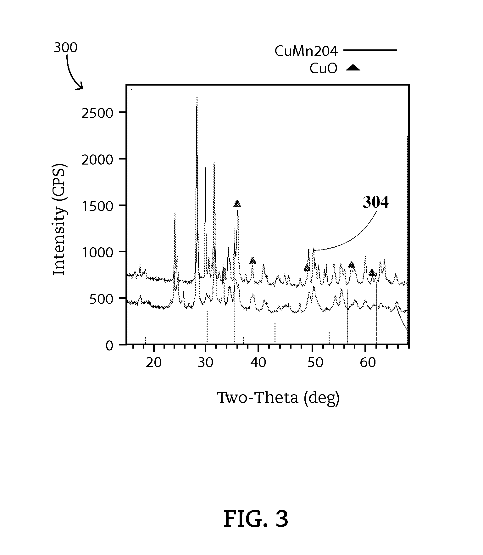
[0059]A ZPGM Cu—Mn powder catalyst, referred as SM1-Type 1, is a stoichiometric Cu1.0Mn2.0O4spinel, Cu—Mn molar ratio of 0.33, supported on ZrO2—Nb2O5. The carrier material oxide contains ZrO2 from 60 to 80 percent by weight, preferably 75 percent by weight and Nb2O5 from 20 to 40 percent by weight, preferably 25 percent by weight. A mixed phase of Cu—Mn spinel and CuO formed at fresh sample which undergoes calcination at 550° C. The Cu—Mn spinel phase is stable during aging at 900° C. The fresh SM1-Type1 catalyst may show a crystallite size of 11 nm and aged SM1-Type1 catalyst may show a crystallite size of 18 nm.
[0060]A ZPGM Cu—Mn powder catalyst, referred as SM1-Type 2, is a stoichiom...
example # 2
Example #2
Templating Method for Stoichiometric ZPGM Cu—Mn Spinel Catalyst Systems
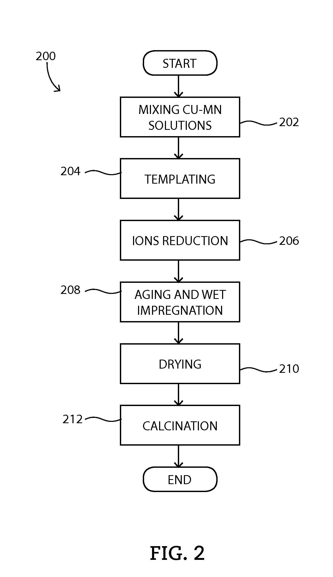
[0061]Example #2 shows ZPGM Cu—Mn powder catalyst of the present disclosure which may be synthesized by templating method 200 using PVP as stabilizer component. Cu—Mn stoichiometric spinels supported on one or more carrier material oxides may be synthesized by templating method 200.
[0062]A ZPGM Cu—Mn powder catalyst, referred as SM2-Type 1, is a stoichiometric spinel of Cu1.0Mn2.0O4, Cu—Mn molar ratio of 0.33, supported on ZrO2—Nb2O5. The carrier material oxide contains ZrO2 from 60 to 80 percent by weight, preferably 75 percent by weight and Nb2O5 from 20 to 40 percent by weight, preferably 25 percent by weight. A mixed phase of Cu—Mn spinel and CuO formed at fresh sample which undergoes calcination at 550° C. The Cu—Mn spinel phase is stable during aging at 900° C. The fresh SM2-Type1 catalyst may show a crystallite size of 9 nm and aged SM2-Type1 catalyst may show a crystallite size of 14 nm. SM2-Typ...
example # 3
Example #3
Templating Method for Non-Stoichiometric ZPGM Cu—Mn Spinel Catalyst Systems
[0064]Example #3 shows ZPGM Cu—Mn powder catalyst of the present disclosure which may be synthesized by templating method 200 using PVP as stabilizer component. Cu—Mn non-stoichiometric spinels supported on one or more carrier material oxides may be synthesized by templating method 200.
[0065]A ZPGM Cu—Mn powder catalyst, referred as SM3-Type 1, is a non-stoichiometric spinel of Cu0.6Mn2.4O4, Cu—Mn molar ratio of 0.2, supported on ZrO2—Nb2O5. The carrier material oxide contains ZrO2 from 60 to 80 percent by weight, preferably 75 percent by weight and Nb2O5 from 20 to 40 percent by weight, preferably 25 percent by weight. A Cu0.6Mn2.4O4 spinel phase formed at fresh sample which undergoes calcination at 550° C. The Cu—Mn spinel phase is stable during aging at 900° C. The fresh SM3-Type1 catalyst may show a crystallite size of 9 nm and aged SM3-Type1 catalyst may show a crystallite size of 14 nm.
[0066]A...
PUM
| Property | Measurement | Unit |
|---|---|---|
| molar ratio | aaaaa | aaaaa |
| molar ratio | aaaaa | aaaaa |
| size | aaaaa | aaaaa |
Abstract
Description
Claims
Application Information