Plasma processing apparatus

Active Publication Date: 2014-12-11
TOKYO ELECTRON LTD +1
View PDF17 Cites 71 Cited by
  • Summary
  • Abstract
  • Description
  • Claims
  • Application Information

AI Technical Summary

Benefits of technology

[0016]In accordance with the example embodiments, since a plasma processing apparatus has a configuration described above, it is possible to simply and securely suppress

Problems solved by technology

However, if the ion energy is lowered at a lower pressure, the non-uniformity of the plasma potential in the entire surface of the substrate may easily cause

Method used


Image

  • Plasma processing apparatus
  • Plasma processing apparatus
  • Plasma processing apparatus

Examples


Embodiment Construction

[0030]In the following, example embodiments will be described, and reference is made to the accompanying drawings, which form a part of the description.

[0031]

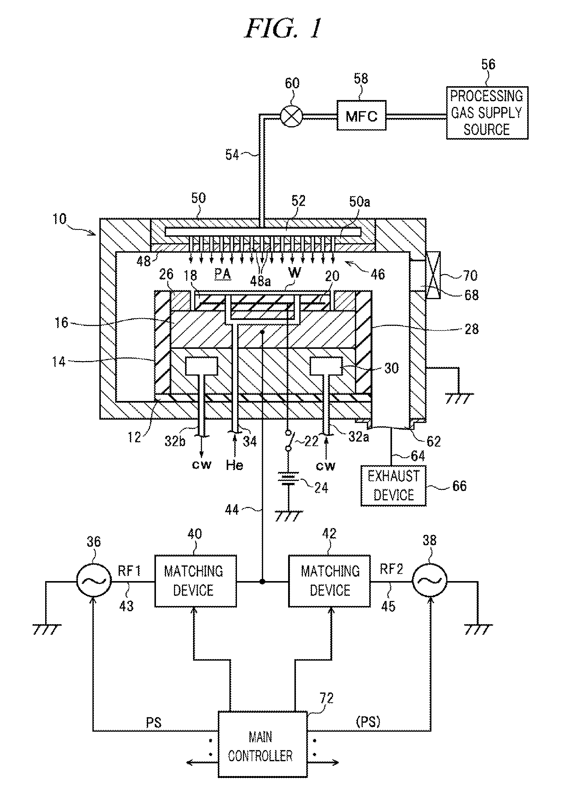
[0032]FIG. 1 is a diagram illustrating a configuration of a plasma processing apparatus in accordance with an example embodiment. The plasma processing apparatus is configured as a capacitively coupled (parallel plate type) plasma etching apparatus. By way of example, the plasma processing apparatus includes a cylindrical decompression chamber (processing vessel) 10 made of, but not limited to, aluminum having an alumite-treated (anodically oxidized) surface. The chamber 10 is grounded.

[0033]A circular columnar susceptor supporting member 14 is provided on an insulating plate 12 such as ceramic on a bottom of the chamber 10, and a susceptor 16 made of, but not limited to, aluminum is provided on the susceptor supporting member 14. The susceptor 16 serves as a lower electrode, and a processing target substrate, e.g., a semicondu...


PUM

PropertyMeasurementUnit
Electrical resistanceaaaaaaaaaa
Frequencyaaaaaaaaaa

Abstract

In a capacitively coupled plasma processing apparatus, a susceptor (lower electrode) 16 within a decompression chamber 10 faces an upper electrode 46 serving as a shower head. The susceptor 16 is electrically connected with a first high frequency power supply 36 and a second high frequency power supply 38 via matching devices 40 and 42, respectively. The first high frequency power supply 36 is formed of a linear amplifier type high frequency power supply and outputs a first high frequency power RF1 for plasma generation. The second high frequency power supply 38 is formed of a switching type high frequency power supply and outputs a second high frequency power RF2 for ion attraction. A residual high frequency power removing unit 74 is connected to a high frequency power supply line 45 on a side of the second high frequency power supply 38.

Description

TECHNICAL FIELD[0001]The embodiments described herein pertain generally to a technology of performing a plasma process on a processing target substrate, and more particularly, pertain to a capacitively coupled plasma processing apparatus method in which a high frequency power for plasma generation is modulated in a pulse shape.BACKGROUND[0002]A capacitively coupled plasma processing apparatus includes an upper electrode and a lower electrode arranged in parallel to each other within a processing vessel. A processing target substrate (e.g., a semiconductor wafer, a glass substrate, etc) is mounted on the lower electrode, and a high frequency power having a frequency (typically, about 13.56 MHz or higher) suitable for plasma generation is applied to the upper electrode or the lower electrode. Electrons are accelerated by a high frequency field generated between the two facing electrodes by applying the high frequency power, and plasma is generated as a result of ionization by collisio...

Claims


Application Information

Patent Timeline
IPC IPC(8): H01J37/32
CPCH01J37/32155H01J37/32183H01J37/32091C23C16/5096C23C16/515H01J37/32165H01J37/32174H05H2242/26
Inventor YAMADA, NORIKAZUTACHIKAWA, TOSHIFUMINAGAMI, KOICHIIKENARI, TATSUYAMAEHARA, DAISUKE
Owner TOKYO ELECTRON LTD
Why Eureka
Try Eureka