Clot removal device

a technology for removing devices and clots, which is applied in the field of endovascular medical devices, can solve problems such as dissection or perforation, abrasion of the inner walls of the vessels, and force required to retract the device may have undesired consequences,

Active Publication Date: 2014-12-18
NEURAVI
View PDF6 Cites 62 Cited by
  • Summary
  • Abstract
  • Description
  • Claims
  • Application Information

AI Technical Summary

Benefits of technology

[0006]The disclosed designs overcome the disadvantages of existing mechanical thrombectomy solutions. In one embodiment a tubular member is slidably disposed on the shaft of a thrombectomy device. The device captures the clot in the engaging body. Once the clot has been captured the device is withdrawn proximally through the vasculature. The withdrawal of the device places pressure on the surrounding vessels and causes abrasion on the inner walls of the vessels. This is the stage at which the highest loads are applied. However the use of a slider tube reduces these forces.
[0007]As it is slidably disposed on the elongate shaft of the thrombectomy device and the coefficient of friction between the tube and elongate shaft is lower than that between the slider tube and the vessel, the slider tube remains in situ as the shaft is retracted. The force that the elongate shaft would normally exert on the vessels is spread over the outer surface area of the tube. Therefore there is less friction within the vessels and this reduces the effects of abrasion.
[0008]The device reduces the friction within the vessel and it also reduces the overall force required to withdraw the elongate shaft. As the level of friction is reduced the forces of compression on the surrounding vasculature are consequently reduced. The slider tube may contain low diameter regions and / or highly flexible regions as described below and these regions increase the flexibility of the tube and thus further reduce the forces on the neighbouring vascular bed. Therefore the overall force required to remove the clot is reduced, which in turn reduces the forces on the vascular bed. Therefore the key benefit of the present invention is a significant reduction in rubbing of the elongate shaft against vessel walls during the initial dislodgement and retraction of the clot.
[0009]An additional benefit of the present invention is the prevention of accidental retraction of the clot retrieval device into the distal end of the microcatheter and subsequent loss of the clot. This could occur should a physician attempt to use the microcatheter in the manner of a slider tube, namely withdraw the clot retrieval device as far as the microcatheter and withdraw the microcatheter a little further and so forth. This increases the possibility of the device being withdrawn into the microcatheter and resuming its collapsed configuration and therefore losing control of the clot. If a slider tube is used the microcatheter is withdrawn a significant distance and the slider tube will automatically start to advance proximally with the device once the distal end of the slider tube contacts the shaft. The process functions thus as there is less energy expended as the device shaft slides through the slider tube compared to the slider tube moving through the vessel. This effect is influenced by the difference in the coefficient of friction between the slider tube and shaft and between the slider tube and vessel, and also by the relative lateral stiffnesses of shaft and slider tube.STATEMENT OF THE INVENTION
[0014]wherein the slider tube can slide freely over the surface of the elongate member between a proximal position and a distal position.
[0016]wherein the slider tube comprises an inner lumen and an outer surface and the inner lumen is sized to slide freely over at least the surface of a distal portion of the elongate structural element.

Problems solved by technology

The force required to retract the device may have undesired consequences.
This relative movement can cause abrasion and damage to the endothelia and underlying layers of the vessel wall, which may result in a dissection or perforation, or could give rise to the subsequent formation of thrombus which could then be liberated to create an additional stroke.
The withdrawal of the device places pressure on the surrounding vessels and causes abrasion on the inner walls of the vessels.
This increases the possibility of the device being withdrawn into the microcatheter and resuming its collapsed configuration and therefore losing control of the clot.

Method used


Image

  • Clot removal device
  • Clot removal device
  • Clot removal device

Examples


Embodiment Construction

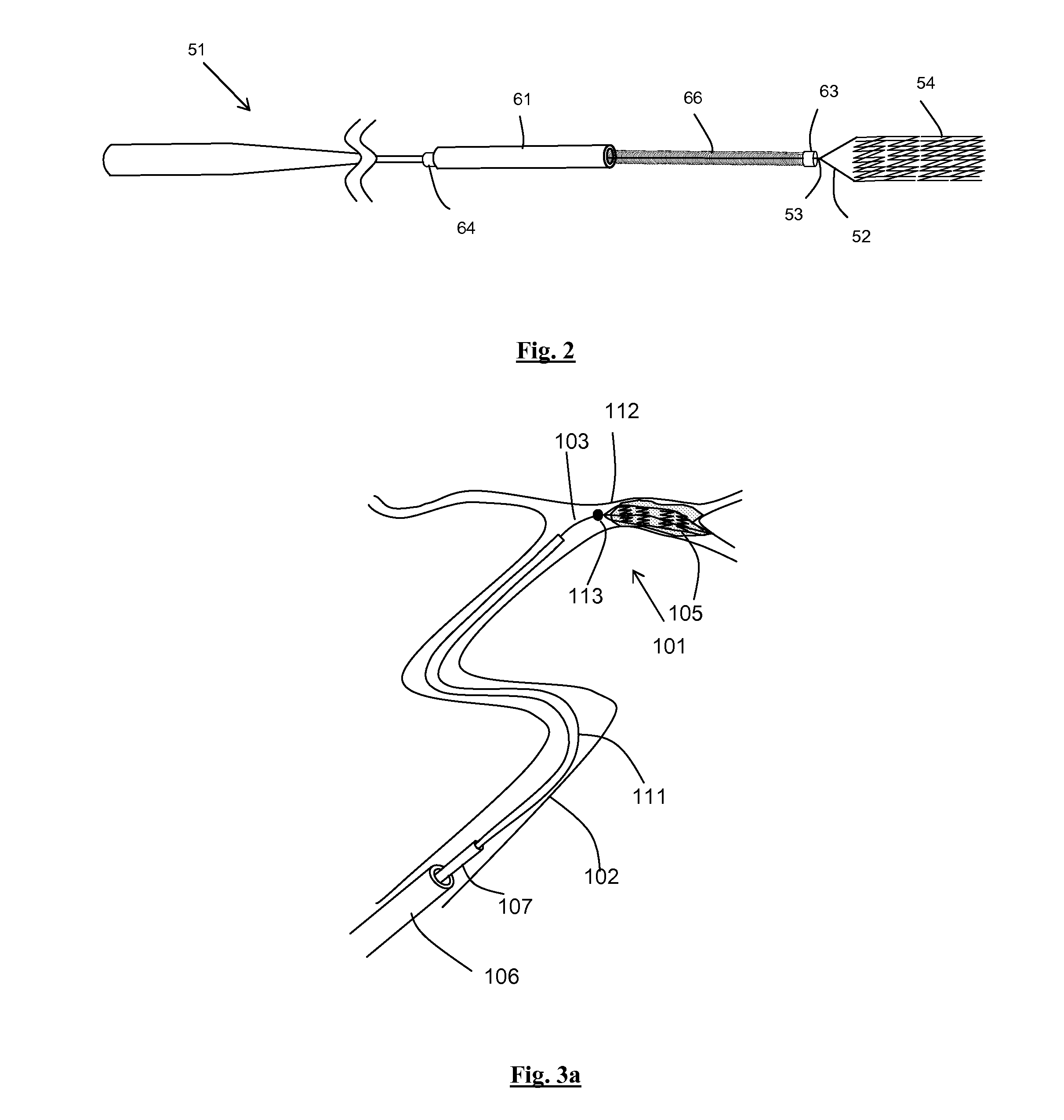
[0080]Specific embodiments of the present invention are now described in detail with reference to the figures, wherein identical reference numbers indicate identical or functionality similar elements. The terms “distal” or “proximal” are used in the following description with respect to a position or direction relative to the treating physician. “Distal” or “distally” are a position distant from or in a direction away from the physician. “Proximal” or “proximally” or “proximate” are a position near or in a direction toward the physician. The invention is applicable to any mechanical thrombectomy clot retrieval device, and a generic design of such a clot retrieval device is shown in the illustrations.

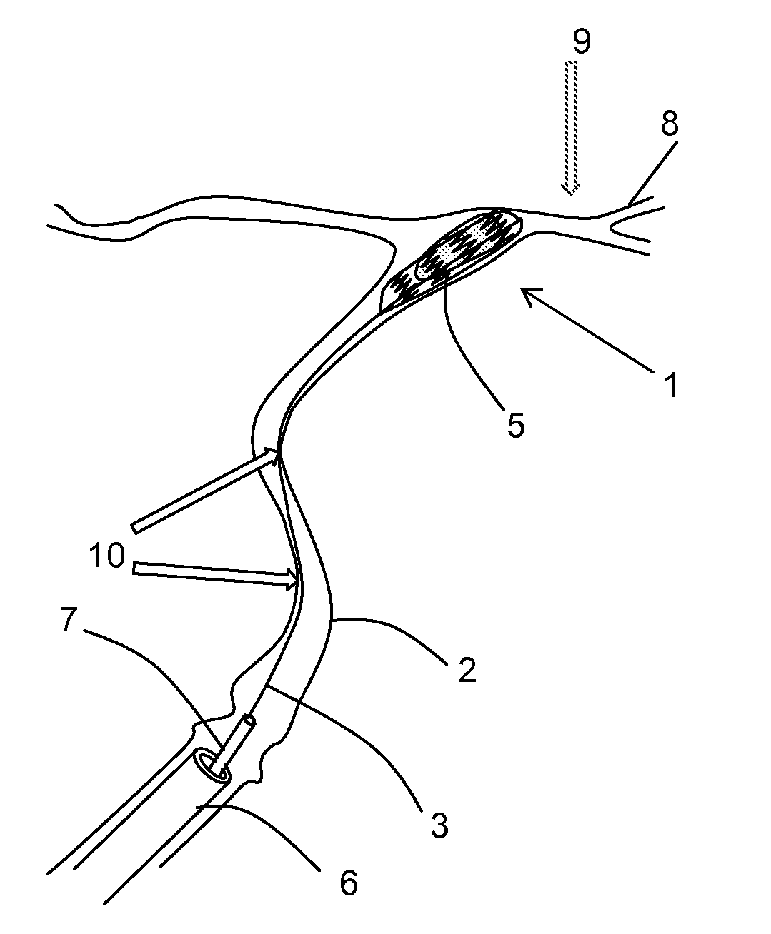
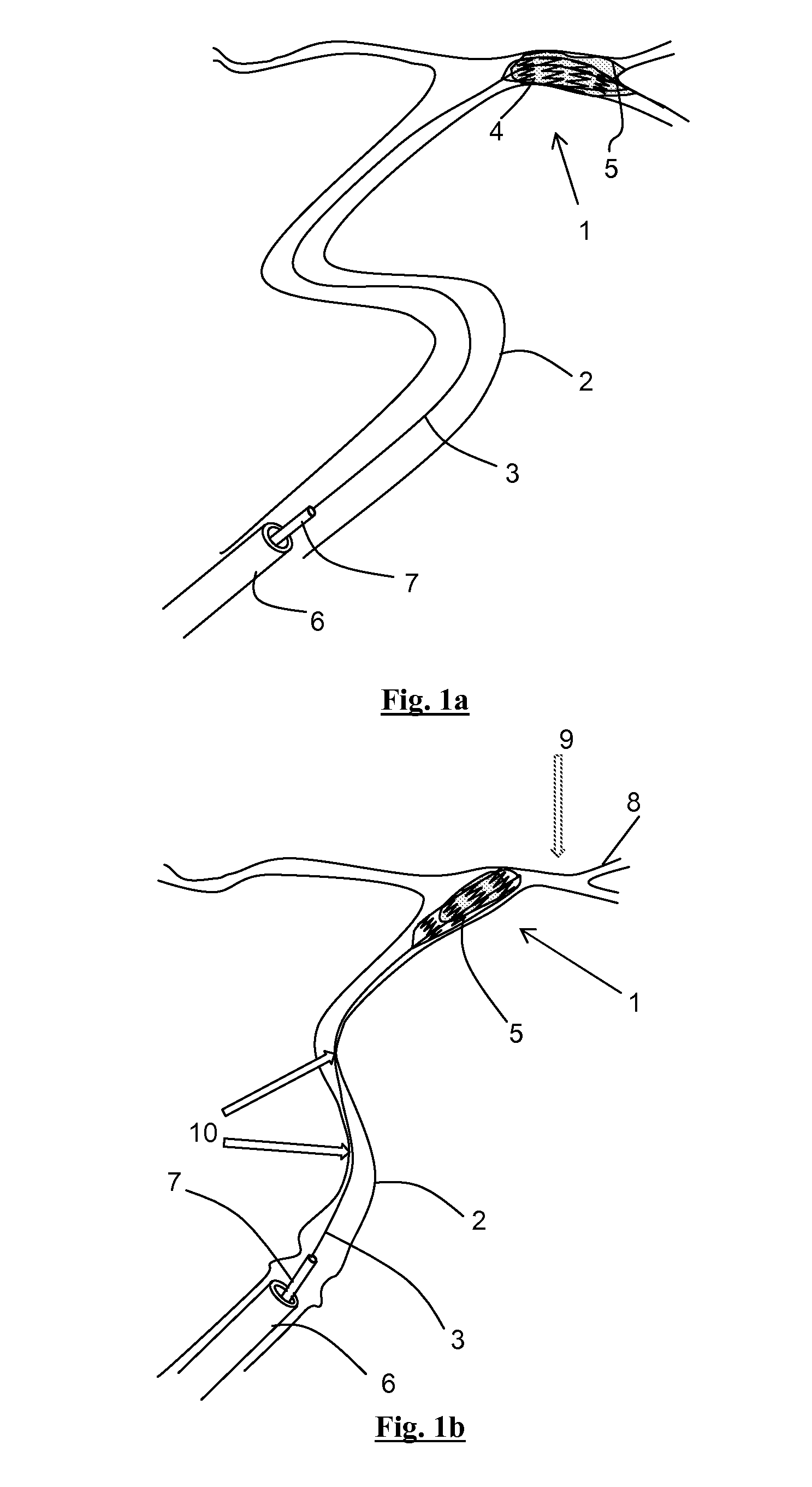
[0081]FIG. 1a-b shows the conventional method of retrieving a clot from tortuous vasculature. A guidewire and microcatheter are inserted into the artery and are advanced across the occlusive clot 5, which is lodged at a bifurcation using any conventionally know techniques.

[0082]The guide...


PUM


Abstract

A system may comprise a clot engagement element having a collapsed delivery configuration and an expanded configuration for engaging with a clot and for dislodging the clot from a first vessel segment. An elongate member may be configured to apply a pull force to the clot engaging element to dislodge the clot from the first vessel segment. A clot removal catheter may include a lumen at its distal end sized to receive the clot and configured to maintain a stable position in a second blood vessel segment proximal of and larger in diameter than the first blood vessel segment. A distal end of the elongate member may be configured to protect a third blood vessel segment between the first and second blood vessel segments from tractive forces transmitted by the elongate member during clot dislodgement from the first vessel segment.

Description

CROSS-REFERENCE TO RELATED APPLICATION[0001]This application claims the benefit of U.S. Provisional Application No. 61 / 780,422, filed Mar. 13, 2013, the disclosure of which is incorporated herein by reference in its entirety.FIELD OF THE INVENTION[0002]This invention relates to endovascular medical devices which are retracted through a portion of the vasculature while in contact with the vessel wall as part of their typical method of use. In particular this invention is of benefit to mechanical thrombectomy devices, vena cava filters, embolic filters, stents and similar devices. For example, it is relevant to clot retrieval devices which are used to retrieve blood clots in the case of ischemic stroke, or in another example, stents which are used to relieve stenosis.BACKGROUND[0003]Mechanical thrombectomy devices such as stentrievers are frequently used to recanalize blocked cerebral arteries in patients suffering from acute ischemic stroke. The method of use of such a device involve...

Claims


Application Information

Patent Timeline
Patent Type & Authority Applications(United States)
IPC IPC(8): A61B17/22
CPCA61B2017/22001A61B17/22031A61B17/221A61B2017/00309A61B2017/00336A61B2017/00853A61B2017/00858A61B2017/2215A61B2090/08021
Inventor VALE, DAVIDBRADY, EAMONGILVARRY, MICHAELCASEY, BRENDAN
Owner NEURAVI
Why Eureka
Try Eureka