Non-aqueous electrolyte secondary battery and method for producing same

a secondary battery and non-aqueous electrolyte technology, applied in the direction of batteries, sustainable manufacturing/processing, cell components, etc., can solve the problems of overcharged state and abnormally high current, and achieve high-precision and stably generated effects, suppressing the degree of polymerization, and producing desirable effects stably

Active Publication Date: 2015-01-01
TOYOTA JIDOSHA KK
View PDF3 Cites 8 Cited by
  • Summary
  • Abstract
  • Description
  • Claims
  • Application Information

AI Technical Summary

Benefits of technology

[0008]While the present inventors examined improvements in the precision and stability of polymerization reactions of overcharge-reactive compounds in non-aqueous electrolyte secondary batteries (e.g. reactions to generate gas or to produce polymers), they discovered that such a reaction occurs mainly in two steps. In particular, in the first step (or Step 1 hereinafter), an overcharge-reactive compound reacts (polymerizes) to produce overcharge-reactive multimers including dimers to higher-order multimers of the overcharge-reactive compound as an intermediate. Subsequently, in the second step (or Step 2 hereinafter), the overcharge-reactive multimers produced further react (polymerize) to produce a polymer. In Step 2, along with the polymerization, atoms foaming a gaseous component are eliminated from the overcharge-reactive multimers, producing a large amount of gas. For instance, however, it is presumed that when the battery is used for a prolonged period or stored at high voltage, part of the overcharge-reactive compound undergoes modification or decomposition and the Step 1 reaction progresses insufficiently. In this case, generation of gas or production of the polymer may become insufficient in Step 2. Based on these studies, further examination was carried out. As a result, it was found out that by allowing the reaction of the overcharge-reactive compound to progress through Step 1 in advance, modification or decomposition of the overcharge-reactive compound could be prevented, making it possible to highly precisely and stably produce desirable effects obtainable by the reaction of the overcharge-reactive compound, whereby the present invention was completed. In the non-aqueous electrolyte secondary battery provided by the present invention, overcharge-reactive multimers including dimers to higher-order multimers formed by polymerization of an overcharge-reactive compound are present in a total amount by mole greater than the overcharge-reactive compound remaining unpolymerized at or near the a positive electrode. The overcharge-reactive compound remaining unpolymerized refers to an overcharge-reactive compound that has not undergone the Step 1 reaction (polymerization). As described above, by allowing the reaction of the overcharge-reactive compound to progress through Step 1 in advance, a significant amount of overcharge-reactive multimers are present at or near the positive electrode at the start of use of the battery. This prevents modification or decomposition of the overcharge-reactive compound. Also, when an overcharged state is reached, the Step 2 reaction readily progresses. Thus, the present invention can highly precisely and stably produce desirable effects obtainable by the reaction of the overcharge-reactive compound.
[0009]In a preferable embodiment of the non-aqueous electrolyte secondary battery disclosed herein, the overcharge-reactive multimers primarily comprise dimers to decamers of the overcharge-reactive compound. In other words, by carrying out the aforementioned Step 1 reaction in advance, at the start of use of the battery, a significant amount of dimers to decamers of the overcharge-reactive compound is present as intermediates at or near the positive electrode. This preferably prevents modification or decomposition of the overcharge-reactive compound. Also, when an overcharged state is reached, the Step 2 reaction readily progresses.
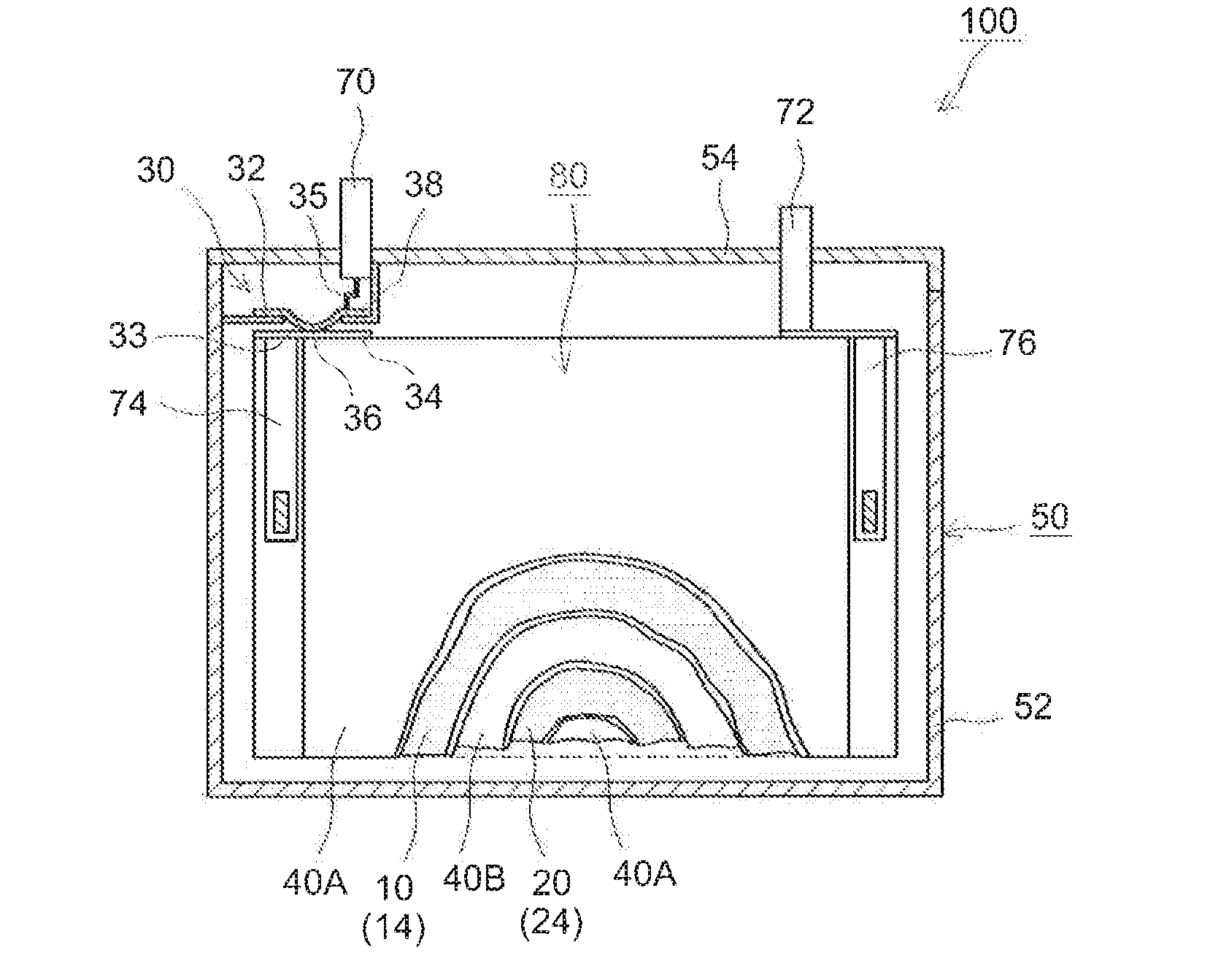
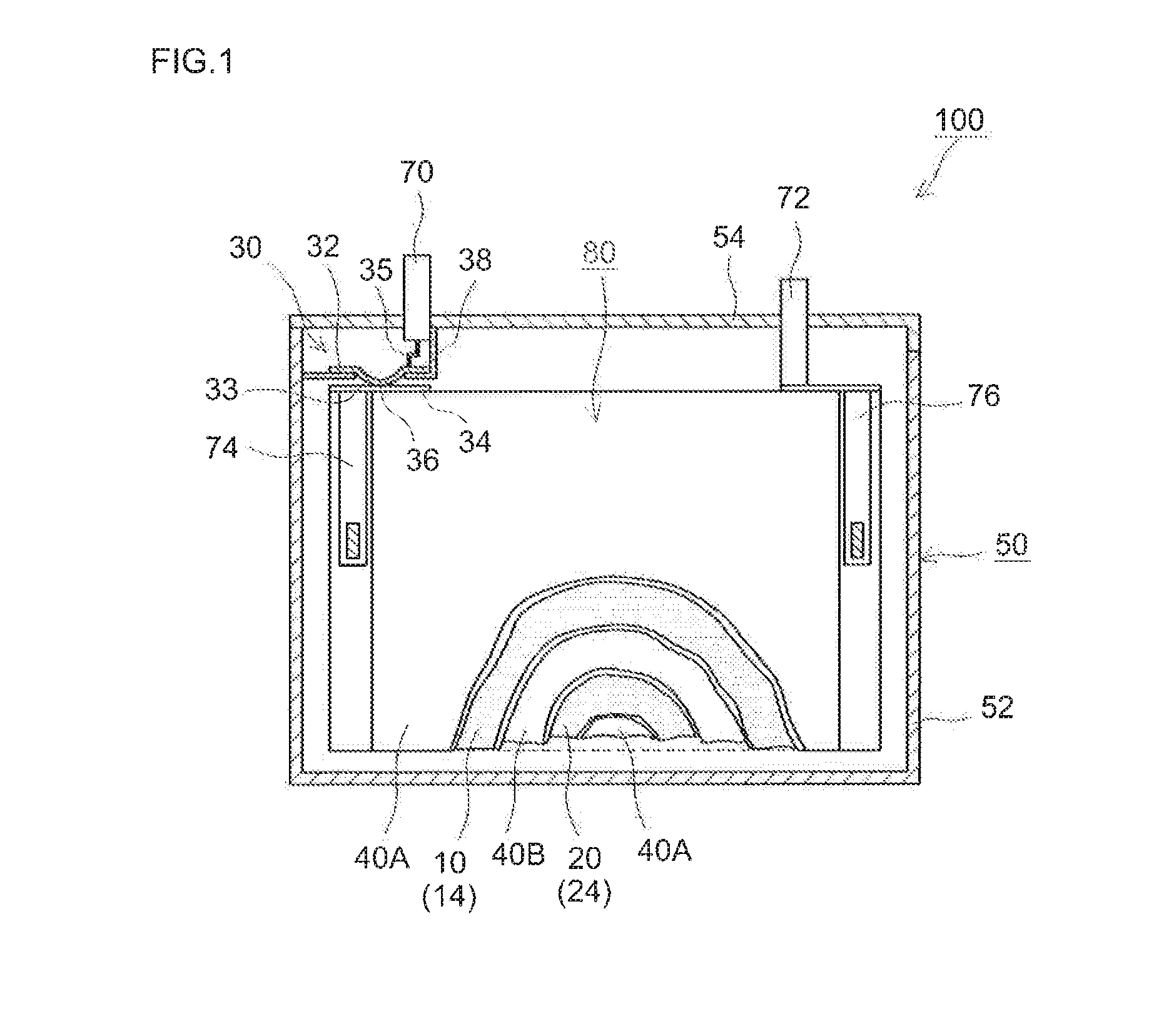
[0012]In a preferable embodiment of the non-aqueous electrolyte secondary battery disclosed herein, the non-aqueous electrolyte secondary battery comprises the positive electrode, a negative electrode and a case to house these electrodes. The battery is constituted as a sealed battery wherein a conductive pathway is formed to allow conduction between at least one of the electrodes and an outer terminal exposed outside the case. The battery further comprises a current-interrupting device configured so that an increase in the internal pressure of the case will cut off the conduction pathway. In the non-aqueous electrolyte secondary battery, by means of the reaction of the overcharge-reactive compound, regardless of the battery condition (e.g. a battery condition such as after prolonged use) or way of use (e.g. a way of use involving storage at high voltage), a necessary amount of gas is generated highly precisely and stably when an overcharged state is reached. This yields an expected increase in the internal pressure of the battery case. Thus, in an embodiment comprising a current-interrupting device that is activated by an internal pressure increase inside the case, the current-interrupting device can be activated highly precisely and stably when an overcharged state is reached. Accordingly, it can be preferably applied to a sealed battery comprising the current-interrupting device.
[0013]The present invention provides a method for producing a non-aqueous electrolyte secondary battery. The production method comprises obtaining a positive electrode comprising a polymerization initiator, obtaining a non-aqueous electrolyte comprising an overcharge-reactive compound, supplying the non-aqueous electrolyte to the positive electrode, polymerizing the overcharge-reactive compound so that overcharge-reactive multimers including dimers to higher-order multimers are formed at or near the positive electrode. As described here, by allowing the reaction of the overcharge-reactive compound to progress through Step 1 in advance with the use of polymerization initiator, modification or decomposition of the overcharge-reactive compound is prevented. Also, when an overcharged state is reached, the Step 2 reaction readily progresses. Hence, the production method of the present invention can provide a non-aqueous electrolyte secondary battery capable of highly precisely and stably producing desirable effects obtainable by the reaction of the overcharge-reactive compound.
[0014]In a preferable embodiment of the production method disclosed herein, the overcharge-reactive multimers primarily comprise dimers to decamers of the overcharge-reactive compound. When the degree of polymerization of the overcharge-reactive multimers produced by the reaction (polymerization) increases excessively, the overcharge-reactive multimers may serve as resistors inside the battery. Thus, it is preferable to suppress the degree of polymerization to a low level. In other words, it is preferable to carry out the Step 1 reaction so that the overcharge-reactive multimers primarily comprise dimers to decamers of the overcharge-reactive compound. By this means, without decreasing the battery properties, modification or decomposition of the overcharge-reactive compound is prevented while the Step 2 reaction progresses readily when an overcharged state is reached.
[0017]A preferable embodiment of the production method disclosed herein comprises constructing a current-interrupting device such that when the internal pressure inside the case housing the positive electrode and a negative electrode is increased, the device cuts off a conduction pathway allowing conduction between at least one of the positive electrode and the negative electrode and an outer terminal exposed outside the case. With respect to the non-aqueous electrolyte secondary battery, by the reaction of the overcharge-reactive compound, a necessary amount of gas is generated highly precisely and stably when an overcharged state is reached, and thus, the internal pressure of the case will also increase as expected. Accordingly, it can be applied to a production method for a secondary battery comprising a current-interrupting device that is activated by an internal pressure increase inside the case as described above.

Problems solved by technology

When this type of battery is subjected to charging, for instance, if the battery being charged has a defect, or if the charger fails and malfunctions, the battery may be supplied with an abnormally high amount of current, resulting in an overcharged state along with some newly formed defects.

Method used


Image

  • Non-aqueous electrolyte secondary battery and method for producing same
  • Non-aqueous electrolyte secondary battery and method for producing same
  • Non-aqueous electrolyte secondary battery and method for producing same

Examples


example 1 to example 8

(1) Fabrication of Positive Electrode Sheet

[0079]Lithium nickel manganese cobalt oxide (Li[Ni1 / 3Mn1 / 3Co1 / 3]O2) powder as a positive electrode active material, acetylene black as a conductive material and polyvinylidene fluoride as a binder were mixed at a mass ratio of these materials of 91:6:3 with N-methyl-2-pyrrolidone. To this, 2,2′-azobisisobutylonitrile (AIBN) as a polymerization initiator was added and mixed in an amount as shown in Table 1 to prepare a pasty positive electrode material layer-forming composition at a non-volatile concentration of about 50% by mass. The composition was evenly applied to a face of a long sheet of aluminum foil (15 μm thick) and allowed to dry to form a positive electrode material layer on the positive current collector, whereby a sheet of positive electrode (positive electrode sheet) was fabricated.

(2) Fabrication of Negative Electrode Sheet

[0080]Natural graphite powder as a negative electrode active material, a styrene-butadiene copolymer as a...


PUM

PropertyMeasurementUnit
temperatureaaaaaaaaaa
thicknessaaaaaaaaaa
conductiveaaaaaaaaaa

Abstract

In the non-aqueous electrolyte secondary battery provided by the present invention, at or near the positive electrode constituting the non-aqueous electrolyte secondary battery, overcharge-reactive multimers including dimers to higher-order multimers formed by polymerization of an overcharge-reactive compound are present in a larger amount by mole than the overcharge-reactive compound remaining unpolymerized.

Description

TECHNICAL FIELD[0001]The present invention relates to a non-aqueous electrolyte secondary battery.Background Art[0002]Lately, lithium-ion secondary batteries and nickel-hydrogen batteries as well as other secondary batteries have become increasingly important as, for example, power supplies loaded on electrically-driven vehicles, or as power sources loaded on PCs, mobile phones and other electric products, etc. One type of structures of these batteries is, for example, a battery having an airtight configuration (sealed battery) obtainable by sealing positive and negative electrodes in a case. When this type of battery is subjected to charging, for instance, if the battery being charged has a defect, or if the charger fails and malfunctions, the battery may be supplied with an abnormally high amount of current, resulting in an overcharged state along with some newly formed defects. Thus, prevention of such defects calls for the use of a battery provided with a device (a current-inter...

Claims


Application Information

Patent Timeline
Patent Type & Authority Applications(United States)
IPC IPC(8): H01M2/34H01M2/24C08G61/02H01M4/62H01M10/058H01M4/04H01M50/529H01M50/534H01M50/574
CPCH01M4/628H01M2/24H01M2/345H01M2200/20H01M10/058C08G61/02H01M2220/20H01M4/04H01M2/34H01M4/62H01M10/0567H01M2/26Y10T29/49108H01M4/13H01M50/574H01M50/534H01M4/0471H01M4/139H01M10/052H01M10/4235Y02E60/10Y02P70/50H01M50/578H01M10/0563H01M2300/002H01M2300/0025H01M10/0565H01M50/529
Inventor MORITA, MASAHIROOYAMA, YUTAKAOKADA, YUKIHIRO
Owner TOYOTA JIDOSHA KK
Why Eureka
Try Eureka