Conductive polymer fuse

a polymer and polymer technology, applied in the field of printed electronics, can solve the problems of inability to disclose whether the fuse is encapsulated, the difficulty of depositing and patterning metal remains, and prior approaches to the problem (e.g., vacuum deposition, photolithography with a metal etchant), so as to improve improve the effect of printed electronic devices, and destroy the electrical conductivity of the polymer

Inactive Publication Date: 2015-01-08
PARKER HANNIFIN CORP
View PDF7 Cites 8 Cited by
  • Summary
  • Abstract
  • Description
  • Claims
  • Application Information

AI Technical Summary

Benefits of technology

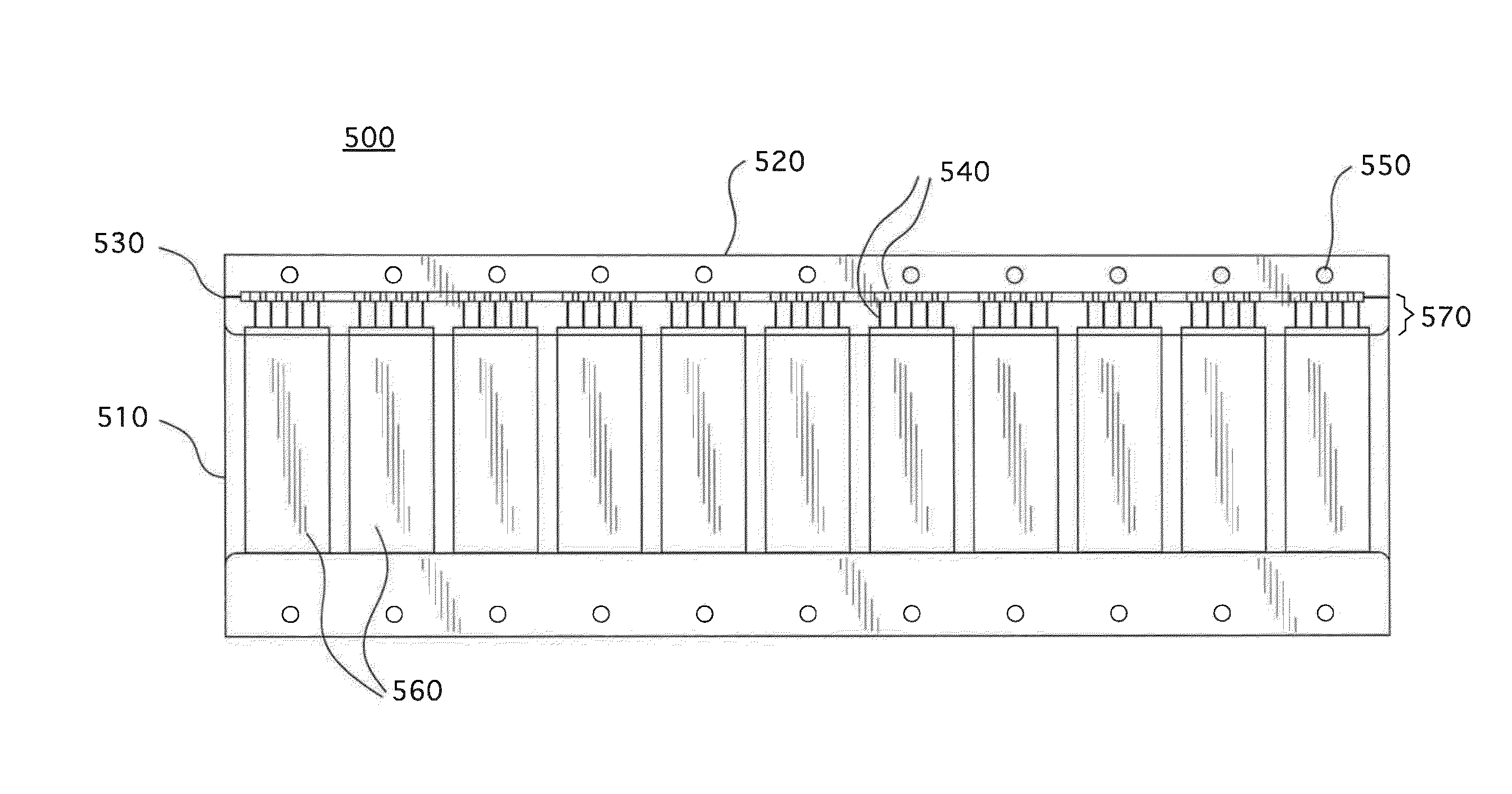
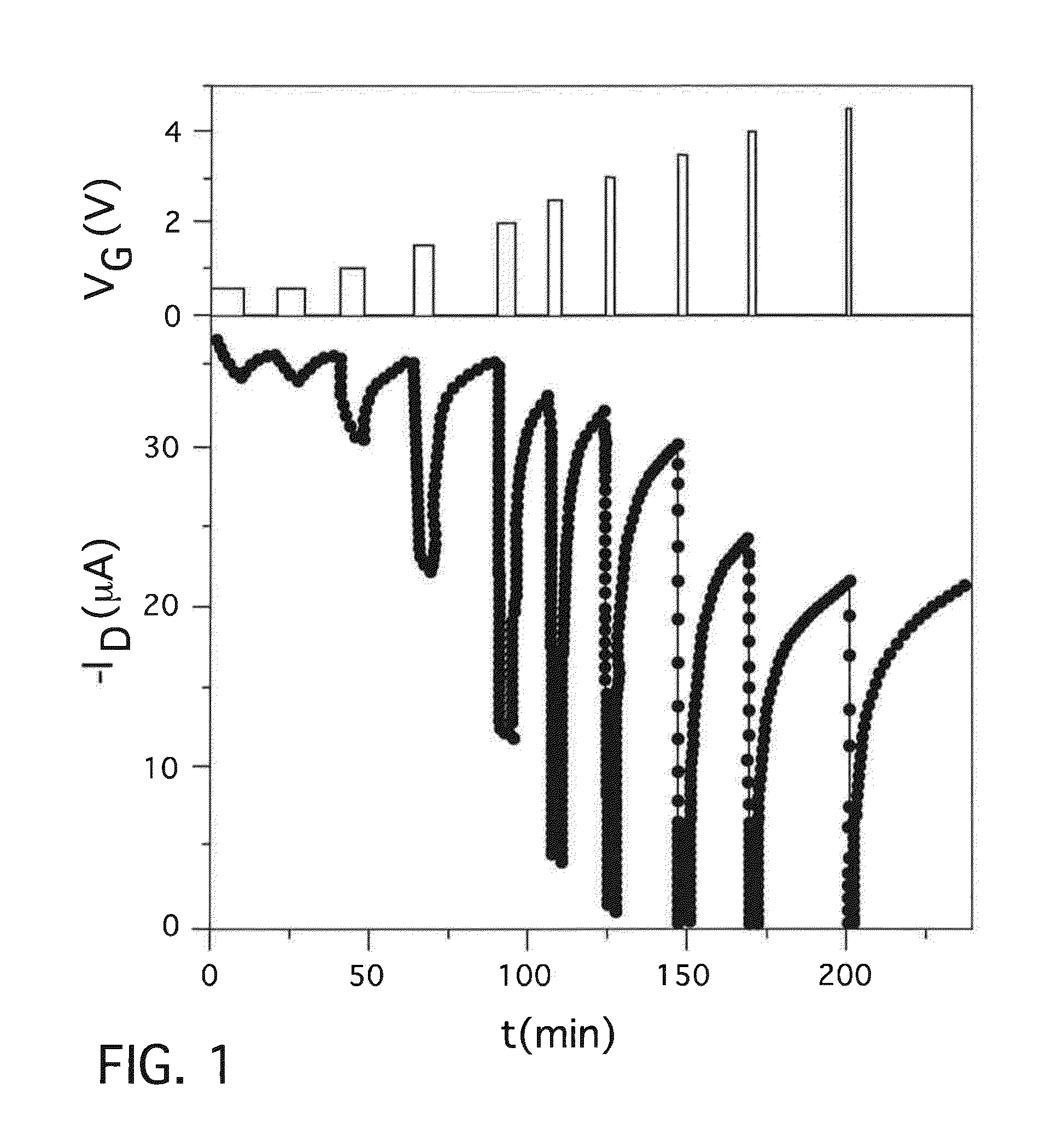
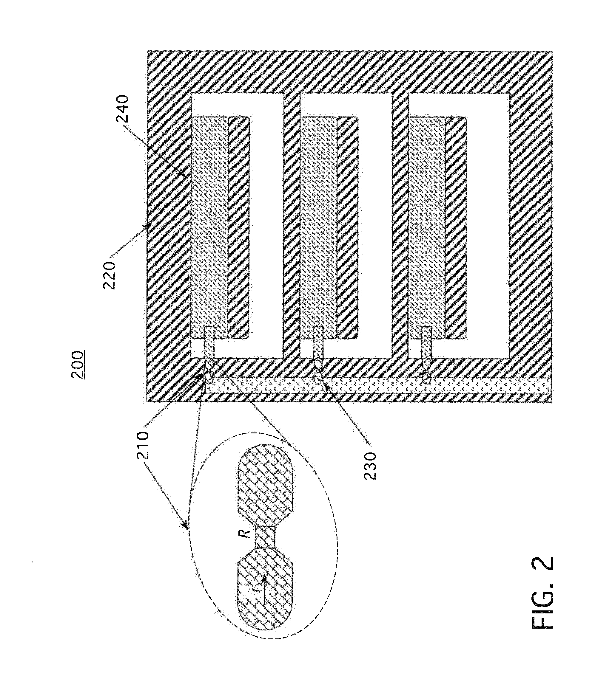
[0008]To circumvent difficulties encountered above, the present inventors disclose a conductive polymer fuse compatible with printed electronics. Unlike conventional fuses that require melting of a metal, this fuse undergoes an irreversible chemical reaction at about 200° C. The reaction destroys the electrical conductivity of the polymer, protecting the rest of the circuit. The conductive polymer fuse of the present invention comprises a substrate having printed thereon poly(3,4-ethylenedioxy-thiophene) / poly(styrene-sulfonate) (PEDOT:PSS) and one or more high conductivity connections, wherein the conductive polymer fuse is encapsulated with an encapsulant. Methods of making the inventive conductive polymer fuses are also provided. Such conductive fuses may find use in improving printed electronic devices by protecting those devices against short circuits.

Problems solved by technology

Unfortunately, conventional fuses are based on melting or evaporation of a solid metal conductor.
Even where low melting temperature alloys are used (e.g., containing tin, lead, indium, gallium, etc.), the difficulty of depositing and patterning the metal remains.
Prior approaches to the problem (e.g., vacuum deposition, photolithography with a metal etchant), are unsatisfactory and can be undesirably expensive.
Finally, MacDiarmid et al. fail to disclose whether their fuses are encapsulated.

Method used


Image

  • Conductive polymer fuse
  • Conductive polymer fuse
  • Conductive polymer fuse

Examples


Embodiment Construction

[0059]Before explaining the disclosed embodiments in detail, it should be noted that the disclosed embodiments are not limited in application or use to the details of construction and arrangement of parts illustrated in the accompanying drawings and description. The disclosed embodiments may be implemented or incorporated in other embodiments, variations and modifications, and may be practiced or carried out in various ways. Further, unless otherwise indicated, the terms and expressions employed herein have been chosen for the purpose of describing the illustrative embodiments for the convenience of the reader and are not for the purpose of limitation thereof. Further, it should be understood that any one or more of the disclosed embodiments, expressions of embodiments, and examples can be combined with any one or more of the other disclosed embodiments, expressions of embodiments, and examples, without limitation. Thus, the combination of an element disclosed in one embodiment and ...


PUM

PropertyMeasurementUnit
temperaturesaaaaaaaaaa
thicknessaaaaaaaaaa
applied voltageaaaaaaaaaa

Abstract

The present invention provides a conductive polymer fuse comprising a substrate having printed thereon poly(3,4-ethylenedioxythiophene) / poly(styrene-sulfonate) and one or more high conductivity connections, wherein the conductive fuse is encapsulated with an encapsulant. Methods for producing the inventive conductive polymer fuses are also provided. Such conductive polymer fuses may find use in improving printed electronic devices by protecting those devices against short circuits.

Description

CROSS REFERENCE TO RELATED APPLICATION[0001]This application claims the benefit, under 35 USC §119(e), of U.S. provisional patent application No. 61 / 472,783 filed Apr. 7, 2011 entitled “CONDUCTIVE POLYMER FUSE”, the entire disclosure of which is hereby incorporated by reference.FIELD OF THE INVENTION[0002]The present invention relates in general to printed electronics and more specifically to a conductive polymer fuse compatible with printed electronics which undergoes an irreversible chemical reaction at about 200° C.BACKGROUND OF THE INVENTION[0003]Printed electronics require protection from short circuits just as conventional electronics do. Unfortunately, conventional fuses are based on melting or evaporation of a solid metal conductor. To melt, most metals require temperatures over 300° C., which are too high for most printed electronic substrates (polyester, polycarbonate, etc.). Even where low melting temperature alloys are used (e.g., containing tin, lead, indium, gallium, e...

Claims


Application Information

Patent Timeline
Patent Type & Authority Applications(United States)
IPC IPC(8): H01H85/046H01B1/12H01H69/02
CPCH01H85/046H01H69/022H01H2229/006H01H2229/004H01B1/127H01C7/028H01C17/06586H01G4/015H01G4/18H01L23/5256H01L2924/0002Y10T29/49107H01L2924/00H01C7/02H01H85/00H02H1/00
Inventor ZARRABI, ALIREZABIGGS, SIMON JAMESJENNINGER, WERNER
Owner PARKER HANNIFIN CORP
Why Eureka
Try Eureka