Reservoir Computing Using Passive Optical Systems

a technology of optical systems and reserve computing, applied in the field of information processing and machine learning, can solve the problems of recurrent neural network systems, notoriously difficult to train, large volume, and inability to meet the needs of users, and achieve good and efficient effects

Active Publication Date: 2015-01-08
UNIV GENT +1
View PDF1 Cites 32 Cited by
  • Summary
  • Abstract
  • Description
  • Claims
  • Application Information

AI Technical Summary

Benefits of technology

[0007]It is an object of embodiments of the present invention to provide good and efficient reservoir computing based on optical systems.
[0008]It is an advantage of embodiments of the present invention that versatile reservoir computing is provided, e.g., a single method and / or device according to embodiments can be suitable for a wide variety of machine learning tasks, e.g., for boolean function learning as well as spoken digit recognition.
[0009]It is an advantage of embodiments of the present invention that an optical computing reservoir is provided, e.g., a passive silicon photonics reservoir chip, which consumes substantially zero power, e.g., does not require energy input except for providing the input and acquiring the output.

Problems solved by technology

This is in contrast to recurrent neural network systems, which are notoriously difficult to train.
However, fibre-based approaches may have the disadvantages of being fairly bulky, being not stable enough to exploit information encoded in the phase component of the light, having a not very flexible interconnection topology and offering poor scalability.
However, the integrated optical chip disclosed by Vandoorne et al. may be not very power efficient, e.g., due to the need for optical amplifiers.
Furthermore, it requires a difficult technology, e.g., complex manufacturing processes and relatively costly components.
Furthermore, such approach may only offer a limited speed, e.g., fundamentally limited by the carrier lifetime.

Method used


Image

  • Reservoir Computing Using Passive Optical Systems
  • Reservoir Computing Using Passive Optical Systems
  • Reservoir Computing Using Passive Optical Systems

Examples


Embodiment Construction

[0048]The present invention will be described with respect to particular embodiments and with reference to certain drawings but the invention is not limited thereto but only by the claims. The drawings described are only schematic and are non-limiting. In the drawings, the size of some of the elements may be exaggerated and not drawn on scale for illustrative purposes. The dimensions and the relative dimensions do not correspond to actual reductions to practice of the invention.

[0049]Furthermore, the terms first, second and the like in the description and in the claims, are used for distinguishing between similar elements and not necessarily for describing a sequence, either temporally, spatially, in ranking or in any other manner. It is to be understood that the terms so used are interchangeable under appropriate circumstances and that the embodiments of the invention described herein are capable of operation in other sequences than described or illustrated herein.

[0050]Moreover, t...


PUM

PropertyMeasurementUnit
bending radiusaaaaaaaaaa
wavelengthaaaaaaaaaa

Abstract

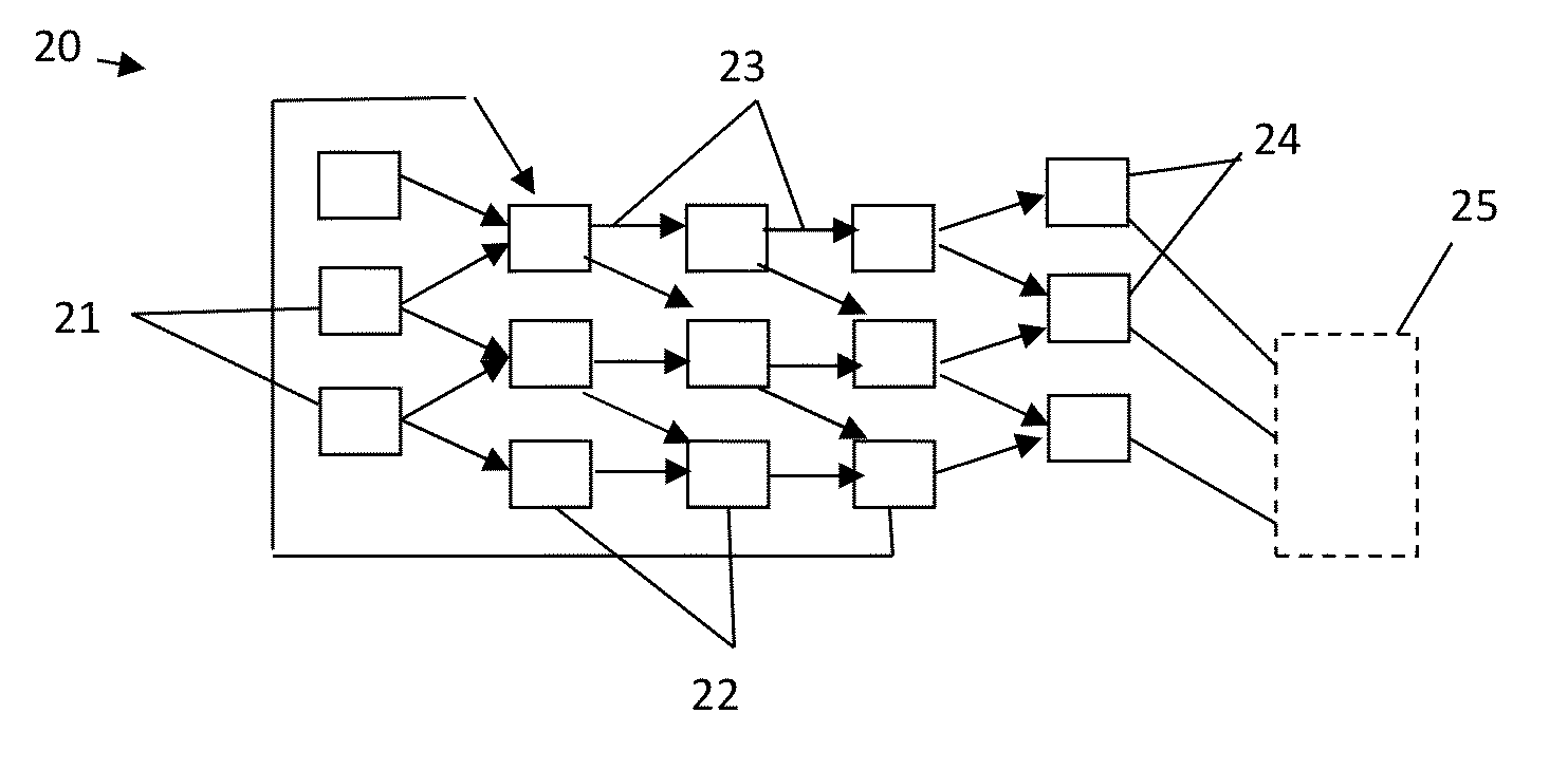
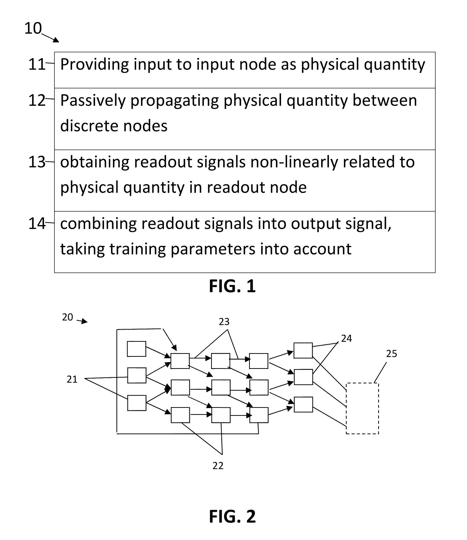
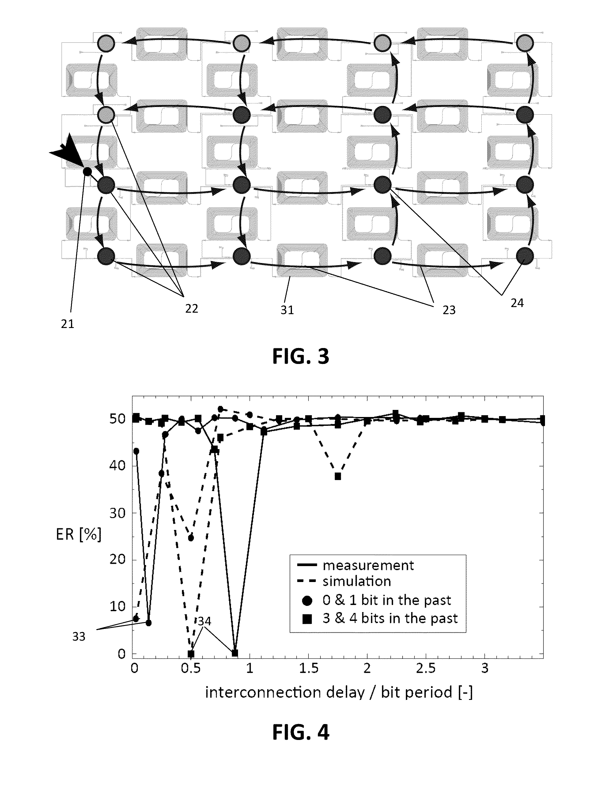
A method comprising providing an input signal to at least one input node of a computing reservoir by temporally encoding the input signal by modulating the at least one photonic wave as function of the input signal is described. The method further comprises propagating the at least one photonic wave via passive guided or unguided propagation between discrete nodes of the computing reservoir, in which each discrete node is adapted for passively relaying the at least one photonic wave over the passive interconnections connected thereto. The method also comprises obtaining a plurality of readout signals, in which each readout signal is determined by a non-linear relation to the at least one photonic wave in at least one readout node of the computing reservoir, and combining this plurality of readout signals into an output signal by taking into account a plurality of training parameters.

Description

FIELD OF THE INVENTION[0001]The invention relates to the field of information processing and machine learning. More specifically it relates to systems and methods for reservoir computing using passive optical systems.BACKGROUND OF THE INVENTION[0002]Nowadays, when one can easily be swamped with data, the relevant question in many applications is no longer how to acquire data, but how to extract the most relevant information from it. Machine learning is a research field dealing with this kind of information processing, and a new paradigm from that field that gained a lot of popularity is Reservoir Computing (RC). The present invention relates to information processing, such as physical information processing, e.g., optical information processing, using this interesting paradigm of reservoir computing. Reservoir computing can find application in the analog domain, e.g., for analog signal classification or for implementing nonlinear analog filters or controllers for which no closed for...

Claims


Application Information

Patent Timeline
Patent Type & Authority Applications(United States)
IPC IPC(8): G02F3/00
CPCG02F3/00G06N3/0675G06N3/08G06N3/044
Inventor BIENSTMAN, PETERDAMBRE, JONIVANDOORNE, KRISTOF
Owner UNIV GENT
Why Eureka
Try Eureka