Bi-component fiber for the production of spunbonded fabric

a technology of fibers and fibers, applied in the field of bicomponent fibers, can solve the problems of additives that can affect the production process, additives can be associated with high costs, additives can be health or environmental hazards, etc., and achieve the effects of improving the softness and/or surface feel of the spunbond fabric, improving the spinning stability and expandability of the fibers, and improving the solidification of the material

Inactive Publication Date: 2015-01-15
EWALD DORKEN
View PDF4 Cites 6 Cited by
  • Summary
  • Abstract
  • Description
  • Claims
  • Application Information

AI Technical Summary

Benefits of technology

[0029]The positive effects of this invention also include the fact that the proportion of recycled materials, which can be added to one of the components in the production of the bi-component fiber, increases relative to conventional fibers. It has been shown that when components with combined melting points according to the invention are used, the change in the properties of a component, which is caused by the addition of recycled material, turns out to be far less than in conventional fibers.
[0030]In this case, the component with the lower melting point preferably forms the outer surface of the fiber in the cross-section of the fiber. The component with the lower melting point preferably surrounds the component with the higher melting point. The effect of this advantageous configuration is that the low-melting component in the sheath area of the fibers ensures better solidification of the material, and, moreover, improves the spinning stability and the expandability of the fibers. As a result, an improvement in the softness and / or surface feel of the spunbond fabric is achieved; in addition, the drapability of the fibers or of a spunbond fabric obtained from the fibers is improved.
[0031]In connection with the invention, it is advantageous when the difference between the melting points of the first component and the second component is at most 6° C. or between 1° C. to 8° C., and preferably between 1° C. to 6° C. Within these advantageous parameter ranges, the positive effects of this invention come significantly strongly to the fore.
[0032]Preferably, the proportion by weight of the component with the lower melting point in the bi-component fiber is at most 50%, more preferably at most 25%, even more preferably at most 10%, and in particular at most 5%. In this case, the bi-component fiber is especially preferably a core-sheath fiber, whereby the component with the lower melting point forms the sheath.
[0033]Advantageously, the difference between the melt-flow indices of the first component and the second component is less than or equal to 25 g / 10 minutes, whereby the melt-flow indices (MFI below) of the first component and the second component in each case are less than or equal to 50 g / 10 minutes. The difference between the melt-flow indices of the first component and the second component is preferably less than or equal to 20 g / 10 minutes, especially preferably 15 g / 10 minutes, and / or the MFIs of the first component and the second component are in each case less than or equal to 40 g / 10 minutes. Such an advantageous selection of the components according to the criterion of their MFIs has a positive effect, surprisingly enough, in a similar way to the selection according to the invention of the components based on their melting points.
[0034]In this case, the MFI is measured according to ISO 1133 with a test load of 2.16 kg and a test temperature of 230° C. The MFI in this case is also referred to as a melt-flow index or else as a melt-mass-flow rate (MFR). The determination is made according to ISO 1133 by the material being melted in a heating cylinder and being pressed by means of the test load through a defined die. The MFI is a measurement of the viscosity of the melts of the respective polymer-containing components. The viscosity in turn is associated with the degree of polymerization, which corresponds to the mean number of monomer units in each molecule of a polymer.

Problems solved by technology

A disadvantage of using these additives, however, is that the additives can disrupt the production process, in particular when they exceed certain overall concentration limits.
In addition, the additives can be associated with high costs.
In addition, additives can be a health or environmental risk, in particular when they exceed overall concentrations in the fibers.

Method used


Image

  • Bi-component fiber for the production of spunbonded fabric
  • Bi-component fiber for the production of spunbonded fabric
  • Bi-component fiber for the production of spunbonded fabric

Examples


Embodiment Construction

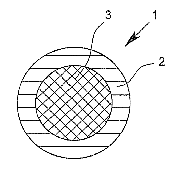
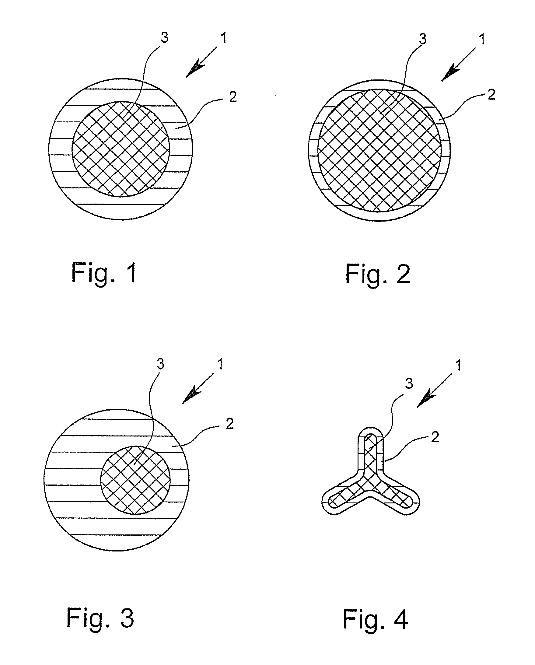
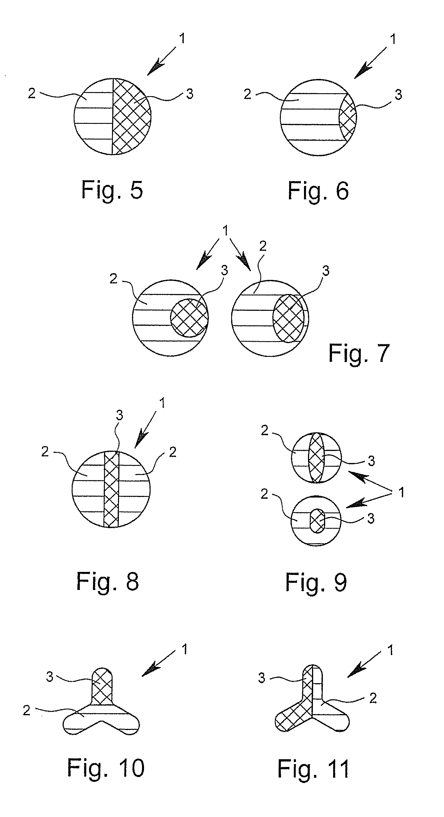
[0093]FIGS. 1 to 16 show cross-sectional views of bi-component fibers 1 according to the invention by way of example. The depicted bi-component fibers 1, in each case, have a first component 2 and a second component 3. In the core-sheath fibers depicted in FIGS. 1 and 4, in this case, the first component 2 surrounds the second component 3 and thus forms the outer surface of the fiber. In this case, the bi-component fibers 1 depicted in FIGS. 1 to 3 have an at least approximately circular or round geometry in cross-section. The bi-component fiber depicted in FIG. 4 shows, however, a trilobal cross-section. Such trilobal cross-sections, like other multilobal cross-sections as well, have the effect that the fiber has a larger outer surface in relation to its mass than is the case with fibers with a circular cross section. In the case of “core-sheath fibers,” in which the proportion of the components forming the sheath is very small, for example approximately 2%, but certainly even in “...


PUM

PropertyMeasurementUnit
melting pointsaaaaaaaaaa

Abstract

A bi-component fiber (1), in particular for the production of spunbond fabrics (4), with a first component (2) and a second component (3), whereby the first component (2) has a first polymer as an integral part and the second component has a second polymer as an integral part. The first component (2) has an additive, and the second component (3) has a percentage by weight of the additive that is smaller than that in the first component (2).

Description

BACKGROUND OF THE INVENTION[0001]1. Field of the Invention[0002]The invention relates to a bi-component fiber, in particular for the production of spunbond fabric, with a first component and a second component, whereby as integral parts, the first component has a first polymer and the second component has a second polymer. In addition, the invention relates to a spunbond fabric with at least one bi-component fiber of the above-mentioned type.[0003]2. Description of Related Art[0004]Bi-component fibers of the type in question usually have a first component that is formed of a first polymer and a second component that is formed of a second polymer. In this case, different types of bi-component fibers can be distinguished, which in each case have different characteristic distributions of the components in the fiber cross-section. Bi-component fibers, in which the first component surrounds and thus encompasses the second component in the cross-section of the fiber, are referred to as co...

Claims


Application Information

Patent Timeline
Patent Type & Authority Applications(United States)
IPC IPC(8): D01F8/04D04H3/16D01F8/18D04H3/007D01F8/06
CPCD01F8/18D01F8/04D04H3/007Y10T428/2929D04H3/16D10B2321/02D01F8/06D01F1/02D01F8/00D04H3/147Y10T442/637
Inventor SCHROER, JORNPLACKE, DANIEL
Owner EWALD DORKEN
Why Eureka
Try Eureka