
Apparatus and method for detecting nir fluorescence at sentinel lymph node

a technology of sentinel lymph node and applicator, which is applied in the field of applicator for observing sentinel lymph nodes, can solve the problems of complex device, inability to see nir fluorescent light with the naked eye, and inability to observe fluorescent light in nir devices, and achieve the effect of high accuracy

Active Publication Date: 2015-01-15
INTHESMART
View PDF7 Cites 46 Cited by
  • Summary
  • Abstract
  • Description
  • Claims
  • Application Information

AI Technical Summary

Benefits of technology

The patent is about a method for improving the accuracy of detecting cancer metastasis during laparoscopic surgery. It involves using a device that irradiates an object with both white light and NIR (infrared) excitation light. The NIR excitation light is controlled to have a discontinuous output, which allows for accurate detection of SLN (semi-lunar nodes) for a short period of time. This improves the accuracy of detecting cancer metastasis and reduces the need for excision ofSLN. The device and method can be easily applied to existing laparoscopes, minimizing the cost of device improvement.

Problems solved by technology

However, such an NIR fluorescent dye cannot be seen with the naked eyes, and thus devices capable of observing NIR fluorescent light have been developed.
However, through the device having the structure described above, the external appearance of an opened organ can be seen only during an abdominal surgery, and there often occurs a confusion among the color of visible light, an ICG fluorescent image in an NIR combined image and an image caused by glare of white light reflected on the surface of a human body.
The device is not suitable for observing fluorescent light in NIR, such as ICG.
However, the synchronization between the light source and the camera makes the device complicated.
However, a specific optical system is required to remove the chromatic aberration in such a manner, and the existing optical couplers cannot be used.
In addition, when a visible light image and an NIR image are respectively displayed in two different screen windows of the same monitor or when the two images are displayed to overlap with each other, it is difficult to distinguish the visible light image from the NIR image.

Method used


Image

  • Apparatus and method for detecting nir fluorescence at sentinel lymph node
  • Apparatus and method for detecting nir fluorescence at sentinel lymph node
  • Apparatus and method for detecting nir fluorescence at sentinel lymph node

Examples


embodiment 1

[0121]In the configuration of a composite image under the condition of a mode in which white reflection light and ICG fluorescence are combined (Reflected White Image+ICG Fluorescence Image), the NIR image fluorescence image is selected other than the image of blue (B) image in a reflection light image background of red (R) and green (G).

[0122]The blue obtained from the white reflection light is not a characteristic element for the image of a tissue, and thus the SLN displayed by the NIR fluorescence is easily distinguished from other tissues. In addition, the SLN is distinguished from hot spots shown in the white reflection light. The white reflection light image forming the image background in the composite image is expressed by only the channels of red (R) and green (G). Since the hot spot has no blue, the hot spot is shown as yellow. Meanwhile, the NIR fluorescence image is shown as blue (B).

[0123]That is, a composite image output using the white reflection light (RG) and the NI...

embodiment 2

[0135]In this embodiment, the intensities of the blue (B) of the white reflection light and the NIR fluorescence are relatively compared for each pixel, so that one of both the blue (B) of the white reflection light and the NIR fluorescence, of which intensity is strong, is selected and output as the blue (B).

[0136]Thus, when the intensity of the blue (B) of the white reflection light is stronger than that of the NIR fluorescence, the blue (B) of the white reflection light is selected, thereby implementing RGB colors of the white reflection light together with the red (R) and the green (G). When the intensity of the NIR fluorescence is stronger than that of the blue (B) of the white reflection light, the NIR fluorescence is selected as the blue (B). Hence, the NIR fluorescence is output as a composite image together with the red (R) and the green (G) of the white reflection light.

[0137]FIG. 8 is a block diagram illustrating an example in which the blue (B) is selectively output by c...

embodiment 3

[0166]Through the temporal modulation method, the output mode of continuous laser is changed into a pulse mode having a repetition rate of 1 to 2 Hz that is much smaller than 15 Hz that is the frame rate of the light detection sensor of the TV system used in the endoscope.

[0167]Thus, the NIR image in the continuous VIS image background is periodically glittered due to the pulse mode.

[0168]In this embodiment, the temporal modulation method is performed separately from the color contrast method, and thus the VIS image maintains perfect colors (RGB). On the other hand, when the temporal modulation method is used together with the color contrast method of Embodiments 1 and 2, the blue (B) can be replaced in the NIR fluorescence image, and thus the VIS image may be formed with the red (R), the green (G), and the NIR fluorescence image. Alternatively, when the intensity of a blue (B) light signal is greater than that of the NIR fluorescence image, the VIS image may be perfectly formed wit...


PUM


Abstract

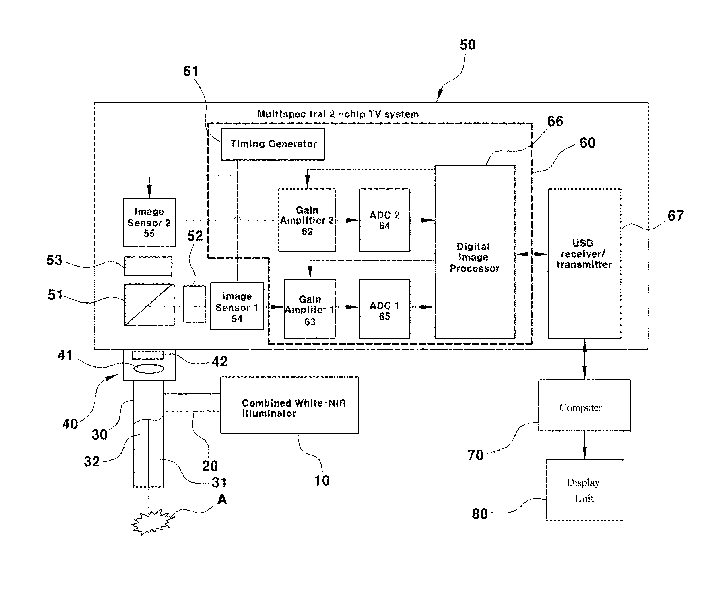
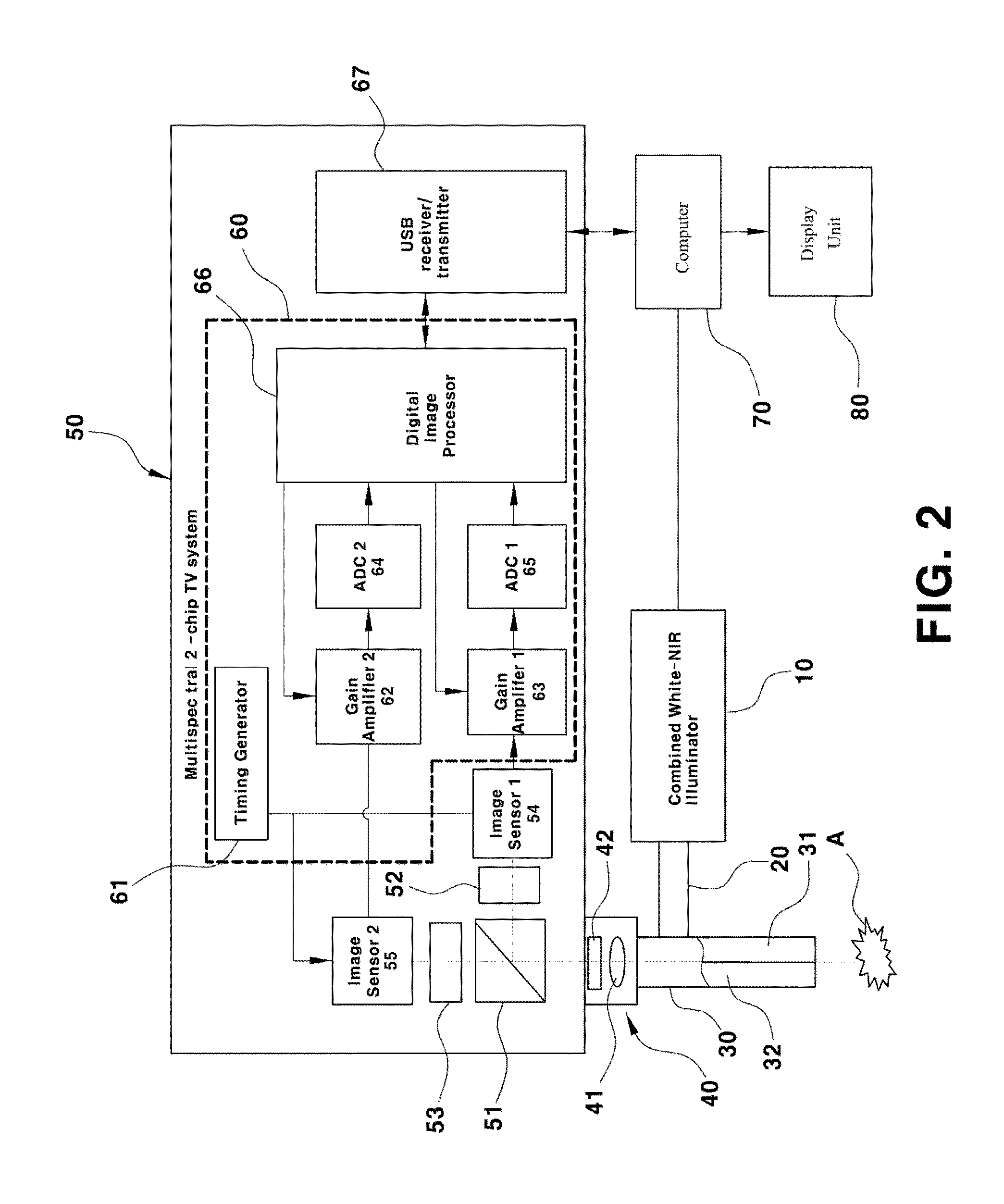
The present invention relates to a device for observing a sentinel lymph node (SLN) in a human body. More particularly, the present invention relates to a device for observing an SLN by detecting near-infrared (NIR) fluorescence caused by a fluorescent material such as indocyanine green (ICG) at the SLN and a method for detecting NIR fluorescence at an SLN. Particularly, in the implementation of a composite image obtained by reproducing a fluorescent material such as ICG and NIR fluorescence emitted by excitation light together with a visible light image, it is possible to detect an SLN with high accuracy through a color contrast method and / or a temporal modulation method using an NIR fluorescence image signal and a visible reflection light image signal.

Description

CROSS-REFERENCE TO RELATED APPLICATION[0001]This application claims under 35 U.S.C. §119(a) the benefit of Korean Patent Application No. 10-2013-0081980 filed Jul. 12, 2013, the entire contents of which are incorporated herein by reference.BACKGROUND[0002](a) Technical Field[0003]The present invention relates to a device for observing a sentinel lymph node (SLN) in a human body. More particularly, the present invention relates to a device for observing an SLN by detecting near-infrared (NIR) fluorescence caused by a fluorescent material such as indocyanine green (ICG) at the SLN and a method for detecting NIR fluorescence at an SLN.[0004](b) Background Art[0005]Sentinel lymph node (SLN) is a lymph node that cancer cells firstly reach when the tumor is directly metastasized via lymph nodes. SLN biopsy is a method for identifying metastasis by finding an SLN through injection of a color pigment into cancer tissue, excising the SLN and then performing a histopathologic examination on t...

Claims


Application Information

Patent Timeline
IPC IPC(8): A61B5/00
CPCA61B5/0071A61B5/0033A61B5/418A61B5/0086A61B1/00009A61B1/0005A61B1/043A61B1/063A61B1/0638A61B5/7425A61B1/00163A61B1/06G01N21/359G01N21/64A61B5/00
Inventor KANG, UKPAPAYAN, GARRY V.
Owner INTHESMART
Learn More