Electric tool

Inactive Publication Date: 2015-01-22
HITACHI KOKI CO LTD
View PDF73 Cites 38 Cited by
  • Summary
  • Abstract
  • Description
  • Claims
  • Application Information

AI Technical Summary

Benefits of technology

[0052]According to the aspect described in (6), since the duty ratio is calculated using operational expressions based on the detected temperature and the detected voltage, change in the duty ratio is gradual. With this configuration, it is possible to prevent occurrence of an unnatural situation where switching of the motor output is suddenly done, even if a plurality of bolt-tightening works is performed. Accordingly, a smooth motor control can be realized.
[0053]According to the aspect described in (7), since the duty ratio is stored in advance as a table which is divided into multiple sections, it is possible to rapidly determine the duty ratio by referring to the table when the rotation switch is turned on.
[0054]According to the aspect described in (8), the electric tool has the low-load operating mode and the high-load operating mode as a control mode of the motor and the controller adjusts the duty ratio based on the detected temperature and the detected voltage only when the motor is in the high-load operating mode. With this configuration, it is possible to reduce the duty ratio by a fine control in accordance with the control mode. Further, the duty ratio is constantly fixed during a low-load work in which the adjustment of the duty ratio is not required. Accordingly, it is

Problems solved by technology

In the electric tool, a problem that temperature rise occurs in a motor body or the semiconductor switching elements of a fixed drive circuit in the motor body due to a continuous operation or overload, and thus thermal damage may be caused in these components or elements constituting these

Method used


Image

  • Electric tool
  • Electric tool
  • Electric tool

Examples


embodiment 1

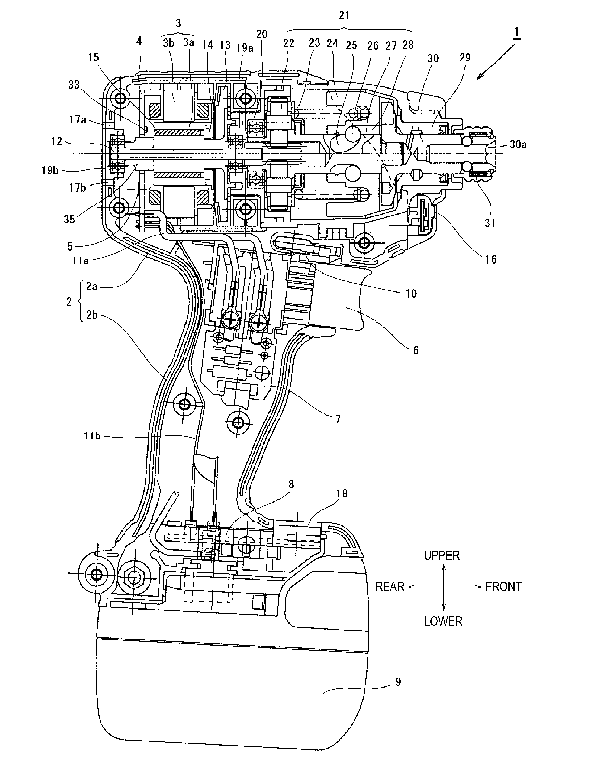
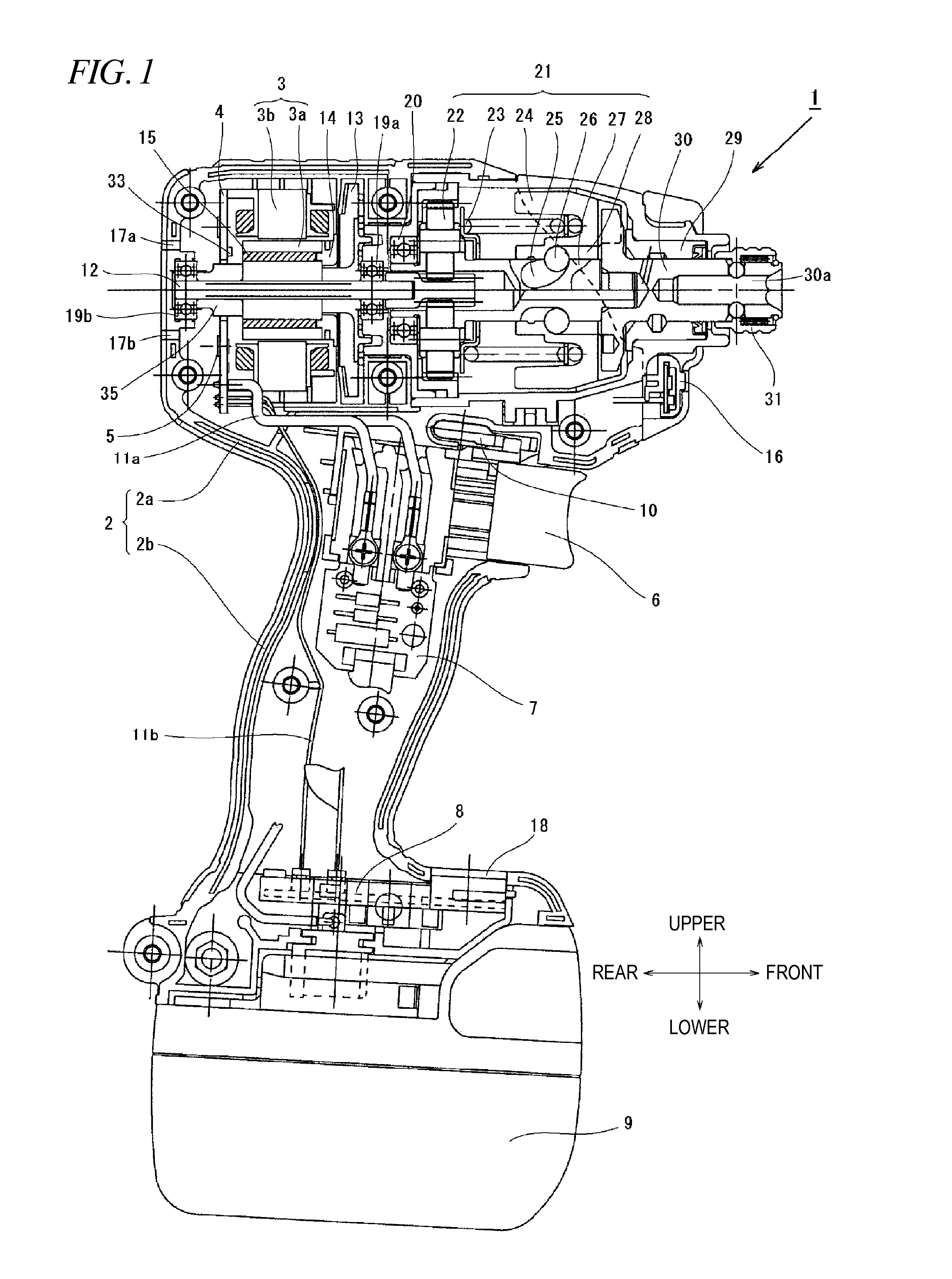
[0069]Hereinafter, exemplary embodiments of the present invention will be described with reference to the accompanying drawings. Further, as used herein, a front-rear direction and an upper-lower direction are referred to the directions indicated by arrows of FIG. 1.

[0070]FIG. 1 is a view showing an internal structure of an impact driver 1 as an example of an electric tool according to the exemplary embodiments. The impact driver 1 is powered by a rechargeable battery 9 and uses a motor 3 as a driving source to drive a rotary striking mechanism 21. The impact driver 1 applies a rotating force and a striking force to an anvil 30 which is an output shaft. The electric tool 1 intermittently transmits a rotational striking force to a tip tool (not shown) such as a driver bit to fasten a screw or a bolt. Here, the tip tool is held on an mounting hole 30a of a sleeve 31.

[0071]The brushless DC type motor 3 is accommodated in a cylindrical main body 2a of a housing 2 which is substantially ...

second embodiment

[0094]Next, a second embodiment of the present invention will be described with reference to FIGS. 6 and 7. In the first embodiment, the duty ratio of the PWM control which performs the speed control of the motor is calculated by the calculation, based on the battery voltage or the motor temperature immediately before the trigger is pulled. In the second embodiment, calculation results of the first embodiment are grouped to some extent and stored in ROM (not shown) which is included in the operation part 40, or the like. In this way, the setting process of the duty ratio is shortened. FIG. 6 is a matrix table showing a relationship among the battery voltage, the motor temperature and the duty ratio. Here, the battery voltage is divided into six steps and the motor temperature is divided into three steps. And, optimal duty ratios are stored on the basis of combination of the battery voltages and motor temperatures. Here, it is preferable that the stored duty ratios are optimal values...


PUM


Abstract

An electric tool for driving a tip tool, the electric tool includes: a removable battery; the brushless motor configured to generate a driving force for driving the tip tool; an inverter circuit configured to supply drive power from the removable battery to the brushless motor using a plurality of semiconductor switching elements; a controller configured to control the inverter circuit to control rotation of the brushless motor; a temperature detector configured to detect a temperature of the brushless motor or the semiconductor switching elements; and a voltage detector configured to detect a voltage of the battery. The brushless motor is driven such that a duty ratio of PWM drive signal for driving the semiconductor switching elements is determined based on relationship between the temperature detected by the temperature detector and the voltage detected by the voltage detector.

Description

TECHNICAL FIELD[0001]The present invention relates to an electric tool and, more particularly, to an electric tool in which a control method of a motor used as a driving source is improved.BACKGROUND ART[0002]A handheld electric tool, especially, a cordless electric tool which is driven by the electric energy accumulated in a battery is widely used. In the electric tool where a tip tool such as a drill or a driver is rotationally driven by a motor to perform a required work, the battery is used to drive a brushless DC motor, as disclosed in JP 2008-278633 A, for example. The brushless DC motor refers to a DC (Direct Current) motor which has no brush (brush for rectification). The brushless DC motor employs a coil (winding) at a stator side and a permanent magnet at a rotor side and has a configuration that power driven by an inverter is sequentially energized to a predetermined coil to rotate the rotor. The brushless DC motor has a high efficiency compared to a motor with a brush an...

Claims


Application Information

Patent Timeline
IPC IPC(8): H02P6/08B25F5/00
CPCH02P6/08H02P29/0044H02P27/08B25B21/02B25F5/00B25B5/147H02P29/021H02P29/0088B25F5/008H02P29/0241H02P29/60H02P29/68
Inventor TAKANO, NOBUHIROHARADA, TETSUHIROIIMURA, YOSHIONISHIKAWA, TOMOMASAUCHIDA, HIROKINAKANO, YOSHIHIRO
Owner HITACHI KOKI CO LTD
Why Eureka
Try Eureka