Advanced composite radome and method of manufacturing

a technology of composite radomes and radomes, applied in the field of radomes, can solve the problems of affecting the transmission of radar, unable to allow the replacement of a single panel, etc., and achieve the effects of reducing water penetration, superior weathering and hydrophobic properties, and reducing the risk of uv exposur

Active Publication Date: 2015-01-22
EBERT COMPOSITES
View PDF5 Cites 33 Cited by
  • Summary
  • Abstract
  • Description
  • Claims
  • Application Information

AI Technical Summary

Benefits of technology

[0008]One or more implementations of the above aspect of the invention involve one or more of the following: the interconnecting edges are thermoformed and taper inwardly and outwardly, and terminate in elongated strips; the elongated strips are co-molded thermoformed elongated composite material strips made of the same composite material as the inner skin of the curved radome composite material panel; the composite material strips include a foam core, an inner skin, an outer skin, and a plurality of three-dimensional fiber bundles extending through and reinforcing the foam core from the inner skin to the outer skin; curved connecting joints interconnecting the plurality of interconnected curved radome composite material panels along the interconnecting edges, each curved connecting joint including an outer spline, an inner spline and a plurality of fasteners holding the outer spline, inner spline and adjacent composite material strips from adjacent radome composite material panels together; the outer spline and the inner spline include respective holes for receiving the fasteners, and the holes of the outer spline and the holes of the inner spline are offset from each other to cause a curved configuration in connected outer spline and inner spline; the outer spline and the inner spline are made of either a thermoplastic composite or a pultruded thermoset composite. The outside splines may have the head of a fastener buried and bonded into the spline, with the same hydrophobic fabric / film applied over the outside of the spline with traditional adhesives. This minimizes water penetration, eliminating upwards of 2500 holes exposed to the potential for rain-water-penetration. Each radome composite material panel includes an outer hydrophobic coating, which could be any number of films or fabrics, however a preferred hydrophobic coating involves co-curing in the composite process a material that has polytetrafluoroethylene (PTFE) on one-side (OS) and woven fiberglass material on the other side. There are a number of companies around the world supply this material, and the PTFE has superior weathering and hydrophobic properties. The fabrics have typically not been co-cured with other composite skins, nor integrated into a sandwich radome, and typically been used for inflatable radomes, incorporating the fabric by itself. The fabrics have shown superior resistance to UV exposure and are self-cleaning. Many have been installed with zero maintenance for 25 years or more. 0; the radome composite materials are RF-transparent A-sandwich composite material panels, although the technology herein could apply to solid or other types of traditional RF-transparent designs; a method of manufacturing the radome includes manufacturing each interconnecting edge of the curved radome composite material panel, one entire interconnecting edge at a time, with an edge forming tool; manufacturing each interconnecting edge includes receiving one entire interconnecting edge at a time by upper and lower curved clamping elements of the edge forming tool; heating the entire interconnecting edge by the upper and lower curved clamping elements of the edge forming tool; forming the entire interconnecting edge by the upper and lower curved clamping elements of the edge forming tool; cooling the entire interconnecting edge with the edge forming tool; manufacturing the radome includes interconnecting the plurality of interconnected curved radome composite material panels along the interconnecting edges with curved connecting joints; the curved connecting joints include an outer spline, and an inner spline, and interconnecting the plurality of interconnected curved radome composite material panels includes coupling adjacent composite material strips from adjacent radome composite material panels together with the outer spline, the inner spline, and a plurality of fasteners that connect the outer spline and the inner spline together; and / or the outer spline and the inner spline include respective holes for receiving the fasteners, and the holes of the outer spline and the holes of the inner spline are offset from each other, and connecting the outer spline and the inner spline together includes connecting the outer spline and the inner spline together so that the holes of the outer spline and the holes of the inner spline are offset from each other so as to cause a curved configuration in connected outer spline and inner spline. This interconnected edge may be thermoformed into other connecting joints such as flat over-lapping flanges (with additional material added for strength or nothing added for strength since in the above aspect of the invention excellent load transfer from the spline to the entire inner and outer skins is provided). Additionally there is a low profile on the splines to prevent water buildup channeling at the connection, and adversely affect radar transmission. An additional feature of the spline is that a single panel can be removed from the interior. Traditional panels with overlapping connecting flanges cannot allow a single panel to be replaced without disassembling several. A further advantage of the interconnecting joint is the low profile and narrow design, minimizing the disruption the joint may have to the rotating radar. Additionally, a tuning material can be added to the splines to achieve a reduction in overall db-loss of the radar, as compared to no tuning material added. The splines can also be pultruded with features that allow the addition of sealing strips, typically silicone rubber with adhesive on one side, facing the spline, such that the sealing strips can be bonded to the splines, prior to installation; the purpose of such sealing strips is of course to minimize or eliminate water intrusion into the radome due to rain, curved radome thermoplastic composite material is made up of e-glass fiber and a heatable thermoplastic resin thermoformed into a specific shape, cooled, and set into a shape post-cooling. The thermoplastic resin is at least one of polyethylene terephthalate glycol-modified (PETG) and polyethylene terephthalate (PET). The inner skin includes two 0.015-0.025 inch thick PETG resin and glass fiber layers, forming a substantially 0.040 inch thick inner skin and wherein the plurality of three-dimensional fiber bundles include ends that are tied and thermocured between the two layers. The outer skin includes one 0.015-0.025 inch thick PETG resin and glass fiber layer and one 0.015-0.025 inch thick fabric layer of hydrophobic material including an outside with PTFE and an inside with woven glass fiber, forming a substantially 0.040 inch thick outer skin, and wherein the plurality of three-dimensional fiber bundles include ends that are tied and thermocured between the two layers. The foam core is PET foam. The interconnecting edges are thermoformed and taper inwardly and outwardly, and terminate in a butt joint, wherein the butt joint is in effect a tooth formed in the shape of a great circle, as defined by a diameter of the radome. The radome forms a rhombic triacontahedron with individual identical panels. The butt joints of two adjoining panels form a contact plane that is substantially at 90 degrees to a surface of the radome.

Problems solved by technology

Additionally there is a low profile on the splines to prevent water buildup channeling at the connection, and adversely affect radar transmission.
Traditional panels with overlapping connecting flanges cannot allow a single panel to be replaced without disassembling several.

Method used


Image

  • Advanced composite radome and method of manufacturing
  • Advanced composite radome and method of manufacturing
  • Advanced composite radome and method of manufacturing

Examples


Embodiment Construction

[0030]With reference to FIGS. 1-11, an embodiment advanced composite radome will be described.

[0031]The family of radomes of interest are the A-Sandwich radomes that are radio frequency (“RF”) transparent, and are generally thinned skinned glass fiber reinforced composite sandwich structures with a foam core. The foam core is RF transparent and is defined as approximately ¼ the wavelength of the radar being covered and protected.

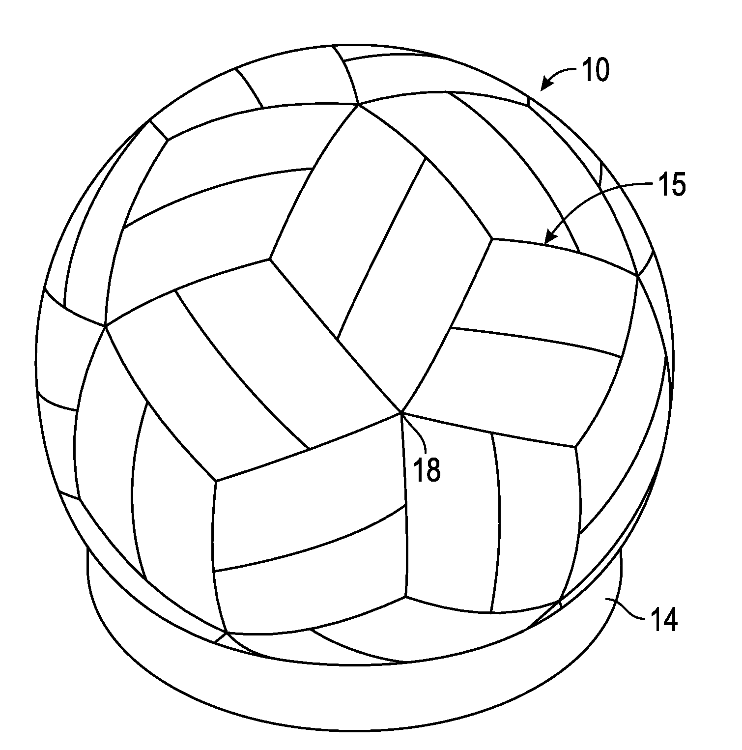
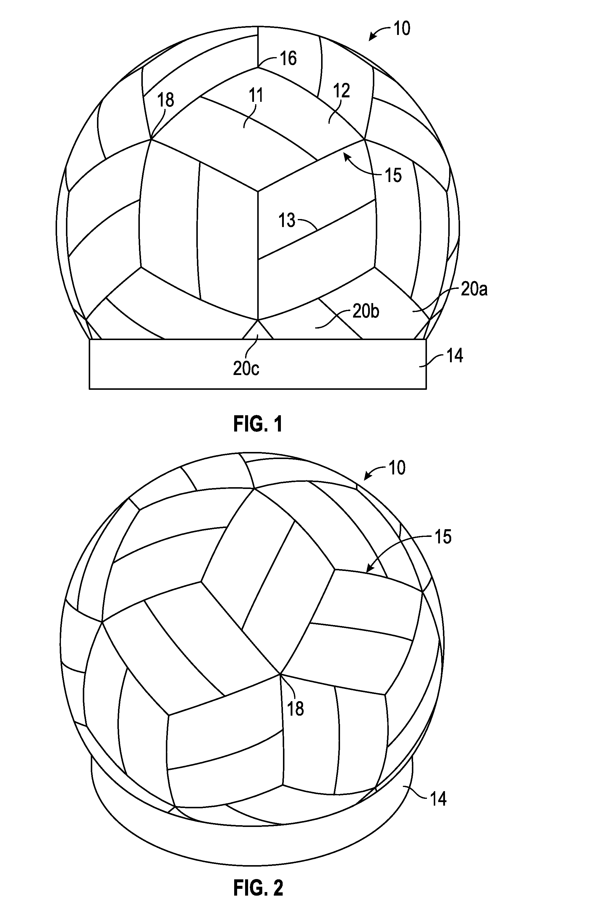
[0032]In FIG. 1, the radome 10 is shown in side elevation with a truncated base. For discussion purposes the specific configuration, diameter, wall thickness and details will be discussed, but, in alternative embodiments, these details and parameters can be changed.

[0033]FIG. 1 is a rhombic triacontahedron design, but clearly could be any of a variety of radome configurations in which panels are defined and connected into a perfect sphere. It turns out a rhombic triacontahedron of the configuration shown has in a full sphere 60 identical panels that when ass...


PUM

PropertyMeasurementUnit
thickaaaaaaaaaa
thickaaaaaaaaaa
diameteraaaaaaaaaa

Abstract

A radome for housing a radar system comprises a plurality of interconnected curved radome thermoplastic composite material panels, each curved radome thermoplastic composite material panel having a plurality of interconnecting edges, a foam core, an inner skin, an outer skin, and a plurality of three-dimensional fiber bundles tying the inner skin and the outer skin to each other through the foam core, inhibiting delamination. The radome includes a hydrophobic exterior surface that is self-cleaning and requires zero maintenance for 25 years.

Description

CROSS-REFERENCE TO RELATED APPLICATIONS[0001]This application claims priority to U.S. Provisional Patent Application No. 61 / 847,914 filed Jul. 18, 2013 under 35 U.S.C. 119 and is incorporated by reference herein.GOVERNMENT LICENSE RIGHTS[0002]This invention was made with government support under Contract Nos. FA8201-08-C-0037, FA8224-10-C-0025, FA8222-12-C-0021 awarded by the United States Air Force. The government has allowed the applicant certain rights in the invention, as this is an Small Business Innovative Research (SBIR) contract. Any government rights, such as “March-In-Rights” would be subject to specific language in the Air Force contract.FIELD OF THE INVENTION[0003]The present invention relates generally to radomes and particularly to radomes made of composite materials.BACKGROUND OF THE INVENTION[0004]The Air Force, as well as many government agencies, utilizes protective radomes to enclose its multitude of land-based radar systems, worldwide. These radomes protect radar...

Claims


Application Information

Patent Timeline
Patent Type & Authority Applications(United States)
IPC IPC(8): B29C53/04H01Q1/42B29C65/56
CPCH01Q1/42B29C53/04B29C65/56B29K2995/0094B29K2309/08B29K2105/256B29K2067/003B29L2031/773B29C65/562B29C66/1142B29C66/43B29C66/543B29C66/71B29C66/721B29C66/7212B29C66/72141B29C66/723B29C66/7392B29C67/0044B29C70/086B29L2031/3456F16B5/0012H01Q1/424B29C66/83221B29C51/268B29C66/73921B29C66/8246B29C66/636B29C66/8242Y10T156/1036B29C69/00G01S7/027B29K2081/04B29K2079/085B29K2077/00B29K2071/00B29K2027/18B29K2023/12
Inventor JOHNSON, DAVID W.GARRETT, SCOTT A.MOYERS, STEPHEN G.
Owner EBERT COMPOSITES
Why Eureka
Try Eureka