Photomask, aberration correction plate, exposure apparatus, and process of production of microdevice

a technology of aberration correction and exposure apparatus, applied in the direction of microlithography exposure apparatus, photomechanical treatment, instruments, etc., can solve the problems of general consideration, increased transmission loss due to absorption and scattering, and optical performance declin

Inactive Publication Date: 2003-11-25
NIKON CORP
View PDF20 Cites 37 Cited by
  • Summary
  • Abstract
  • Description
  • Claims
  • Application Information

AI Technical Summary

Problems solved by technology

If ordinary silica glass is used for light of a wavelength less than about 200 nm, however, the transmission loss increases due to absorption and scattering.
Further, the optical performance declines due to heat buildup resulting from absorption and to the fluorescence.
It was generally considered difficult to use a photomask made of ordinary silica glass for light of shorter wavelengths.
Use as a photomask is problematic in that the photomask is susceptible to damage during transport and the dust generated from the damaged locations is liable to cause unwanted foreign matter to deposit on the pattern and prevent exposure of the desired pattern.
Further, fluorite has a low resistance to temperature changes, is fragile and easily scratched, is damaged during the process of pattern formation, and has a higher coefficient of linear expansion compared with quartz, so special control and countermeasures are required for forming a mask pattern with a high precision.
Similar problems arise as with the above photomask for this aberration correction plate as well.
Further, the problems relating to the photomask and aberration correction plate hinder shortening of the wavelength of the exposure apparatus, make dealing with the increasing miniaturization of patterns to be formed on photosensitive substrates difficult, and make realization of stable exposure performance over time and provision of an exposure apparatus with a long service life hard.

Method used


Image

  • Photomask, aberration correction plate, exposure apparatus, and process of production of microdevice
  • Photomask, aberration correction plate, exposure apparatus, and process of production of microdevice
  • Photomask, aberration correction plate, exposure apparatus, and process of production of microdevice

Examples


first embodiment

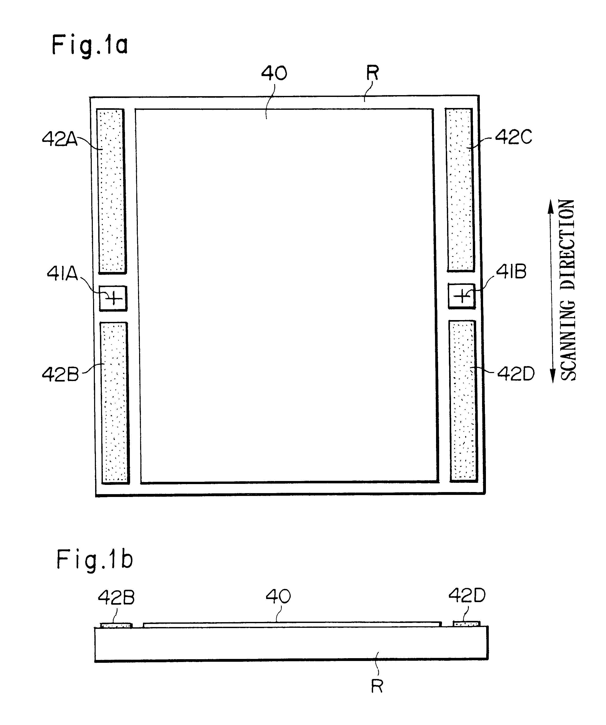
Below, a first embodiment of the present invention will be explained with reference to FIG. 1a and FIG. 1b. FIG. 1a shows the pattern surface of a reticle R of the present example used as a photomask, while FIG. 1b is a side view of the same. In FIG. 1a and FIG. 1b, the reticle R is comprised of a flat substrate made of fluorite as the calcium fluoride (CaF.sub.2) on which a pattern to be transferred, predetermined protective films, etc. are formed. That is, the pattern to be transferred is formed at a pattern region 40 at the center of the pattern surface (bottom surface) of the reticle R. Further, at the two sides of the pattern region 40 are formed reticle alignment marks 41A and 41B for positioning the reticle R with respect to the exposure apparatus (pattern transfer apparatus). Further, above and below the reticle alignment marks 41A and 41B are for example formed protective films 42A to 42D comprised of the same material as the material forming the pattern to be transferred.

N...

second embodiment

1. Overall Configuration

FIG. 4 is a view of the general configuration of a step-and-scan type projection exposure apparatus of a second embodiment of the present invention. Parts of substantially the same configuration as the first embodiment (FIG. 3) are assigned the same reference numerals and explanations thereof are omitted.

The difference from the projection exposure apparatus explained in the first embodiment (FIG. 3) is that the reticle holder 20D for holding the reticle R by suction is carried on the reticle stage 20A through a plurality of (for example, four) expandable and contractible drive elements (piezoelectric elements etc.) 20C. Note that in FIG. 4, the illustration of the reticle base (reference numeral 20B of FIG. 3) on which the reticle stage 20A is arranged is omitted. Further, the aberration correction plate 38 is arranged between the reticle R and the projection optical system PL as explained later.

2. Correction of Imaging Characteristics

The apparatus of FIG. 4 ...

third embodiment

Next, an explanation will be given of a third embodiment of the present invention with reference to the drawings. The projection exposure apparatus of the third embodiment is substantially the same in overall configuration as the projection exposure apparatus of the first or second embodiment (FIG. 3 or FIG. 4). In this embodiment, the structure of the reticle R and the holding structure for the same are specially designed. Therefore, details of the projection exposure apparatus will be omitted.

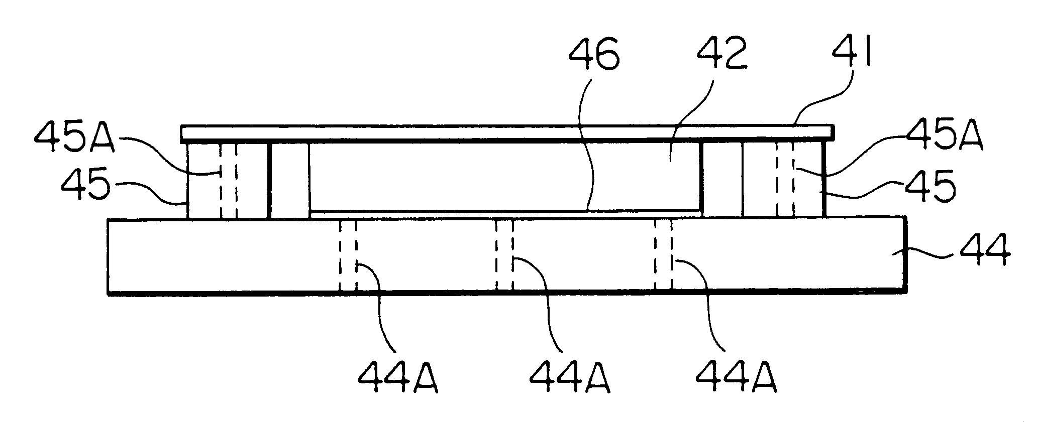
FIG. 7a and FIG. 7b are views of the configurations of the reticle R and reticle holder 20D of the third embodiment. FIG. 7a is a front view and FIG. 7b is a plane view. In FIG. 7a and FIG. 7b, the reticle R serving as the photomask is provided with a glass substrate 41 comprised of a thin sheet of synthetic silica glass and a reinforcing substrate (reinforcing member) 42 comprised of a sheet of fluorite (CaF.sub.2). The pattern to be transferred and the reticle alignment marks etc. are forme...


PUM

PropertyMeasurementUnit
wavelengthaaaaaaaaaa

Abstract

A photomask including a substrate comprised of fluorite (calcium fluoride (CaF2)) and protective films comprised of chrome (Cr), chromium oxide (Cro), silicon oxide (SiO2 or SiO), etc. and formed at regions, other than the pattern region where the pattern to be transferred is formed, which contact other members when transporting the photomask or using it for exposure.

Description

1. Field of the InventionThe present invention relates to an exposure apparatus used when producing for example a semiconductor device, an imaging device, a liquid crystal display, a thin film magnetic head, or another microdevice and to a photomask and aberration correction plate used for the exposure apparatus and a process of production of such a microdevice.2. Description of the Related ArtIn the photolithographic process for producing a semiconductor device etc., use is made of an exposure apparatus to transfer a pattern image of a photomask (including reticle) on to a photosensitive substrate through a projection optical system. The photomask used for such an exposure apparatus is generally produced using silica glass (quartz glass). Silica glass has a low transmission loss of light, has resistant to temperature changes, is excellent in corrosion resistance and elastic performance, has a small coefficient of linear expansion (about 5.5.times.10.sup.-7 / K), and has other superi...

Claims


Application Information

Patent Timeline
Patent Type & Authority Patents(United States)
IPC IPC(8): G03F7/20G03F1/14G03F1/08G03F1/00G03F1/48
CPCG03F1/14G03F7/70866G03F7/707G03F1/48G03F1/08G03F1/50
Inventor SHIRAISHI, NAOMASATAKEUCHI, HITOSHIOWA, SOICHI
Owner NIKON CORP
Why Eureka
Try Eureka