
Flux for laser welding

a laser welding and laser welding technology, applied in the field of metal joining, can solve the problems of limited hot box welding, difficult to weld materials, and difficult to repair applications,

Inactive Publication Date: 2015-01-29
SIEMENS ENERGY INC
View PDF3 Cites 41 Cited by
  • Summary
  • Abstract
  • Description
  • Claims
  • Application Information

AI Technical Summary

Benefits of technology

The patent text describes a method for welding superalloy materials using laser energy and a flux material. The technical effect of this invention is to provide a more effective and reliable method for welding these materials, which are difficult to weld due to their susceptibility to cracking. The use of flux materials in laser welding has not been previously known. The method can be used for repair and additive manufacturing of these materials, and can also be used in combination with other techniques such as preheating and hot box welding. The method can be applied to a variety of superalloy materials and can be used in a variety of welding applications.

Problems solved by technology

It is recognized that superalloy materials are among the most difficult materials to weld due to their susceptibility to weld solidification cracking and strain age cracking.
However, hot box welding is limited by the difficulty of maintaining a uniform component process surface temperature and the difficulty of maintaining complete inert gas shielding, as well as by physical difficulties imposed on the operator working in the proximity of a component at such extreme temperatures.
However, this technique is not practical for many repair applications where the geometry of the parts does not facilitate the use of a chill plate.
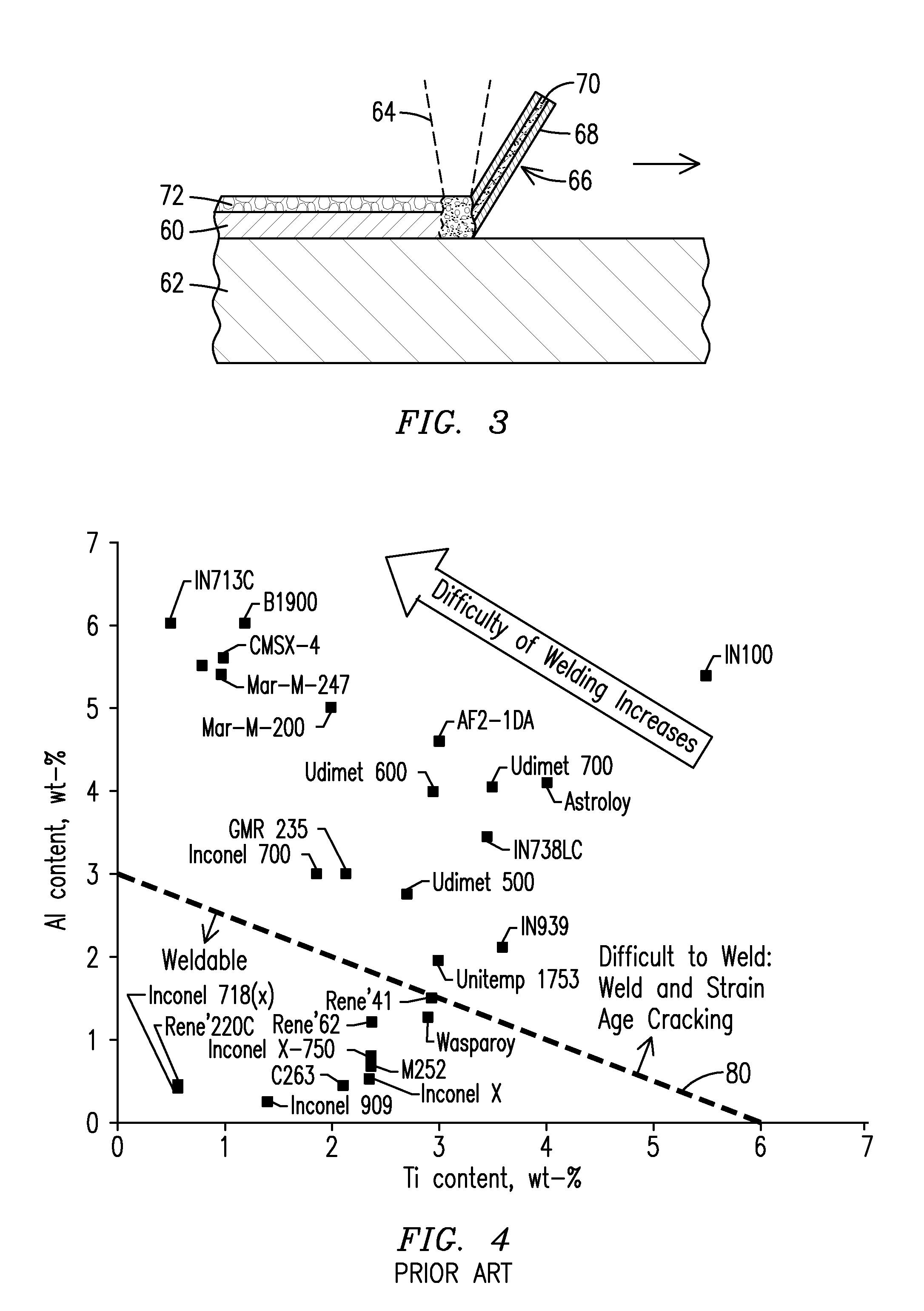
Within the zone of non-weldability, the alloys with the highest aluminum content are generally found to be the most difficult to weld.
These processes tend to trap the oxides (e.g. aluminum and chromium oxides) that are adherent on the surface of the particles within the layer of deposited material, resulting in porosity, inclusions and other defects associated with the trapped oxides.
As new and higher alloy content superalloys continue to be developed, the challenge to develop commercially feasible joining processes for superalloy materials continues to grow.

Method used


Image

  • Flux for laser welding
  • Flux for laser welding
  • Flux for laser welding

Examples


Embodiment Construction

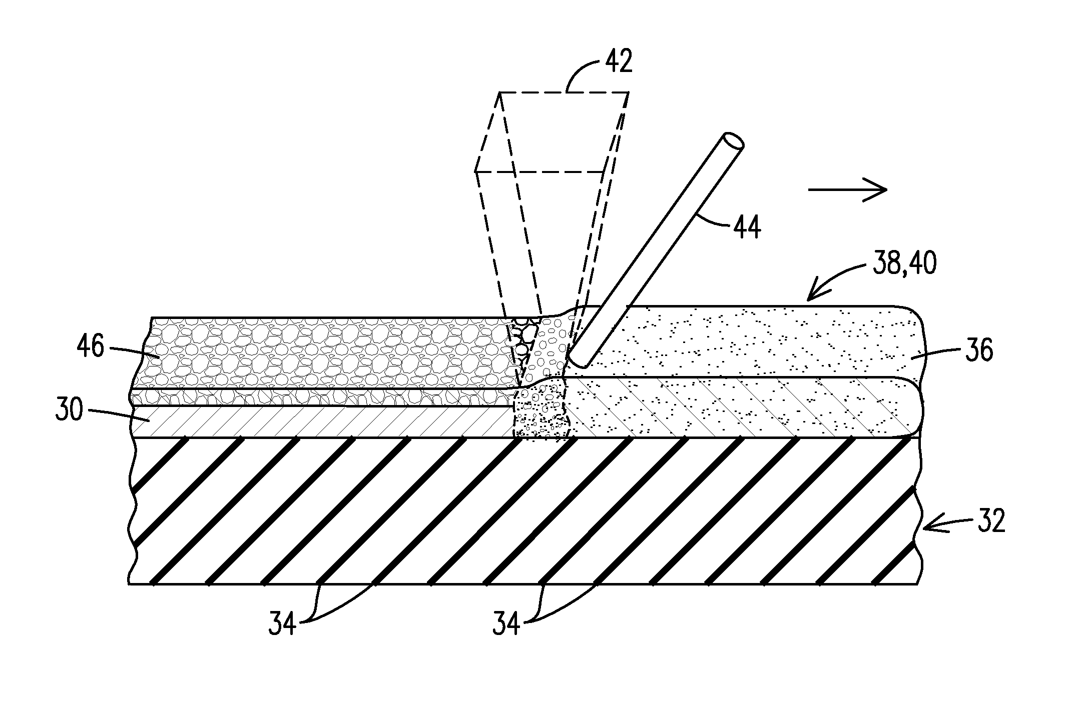
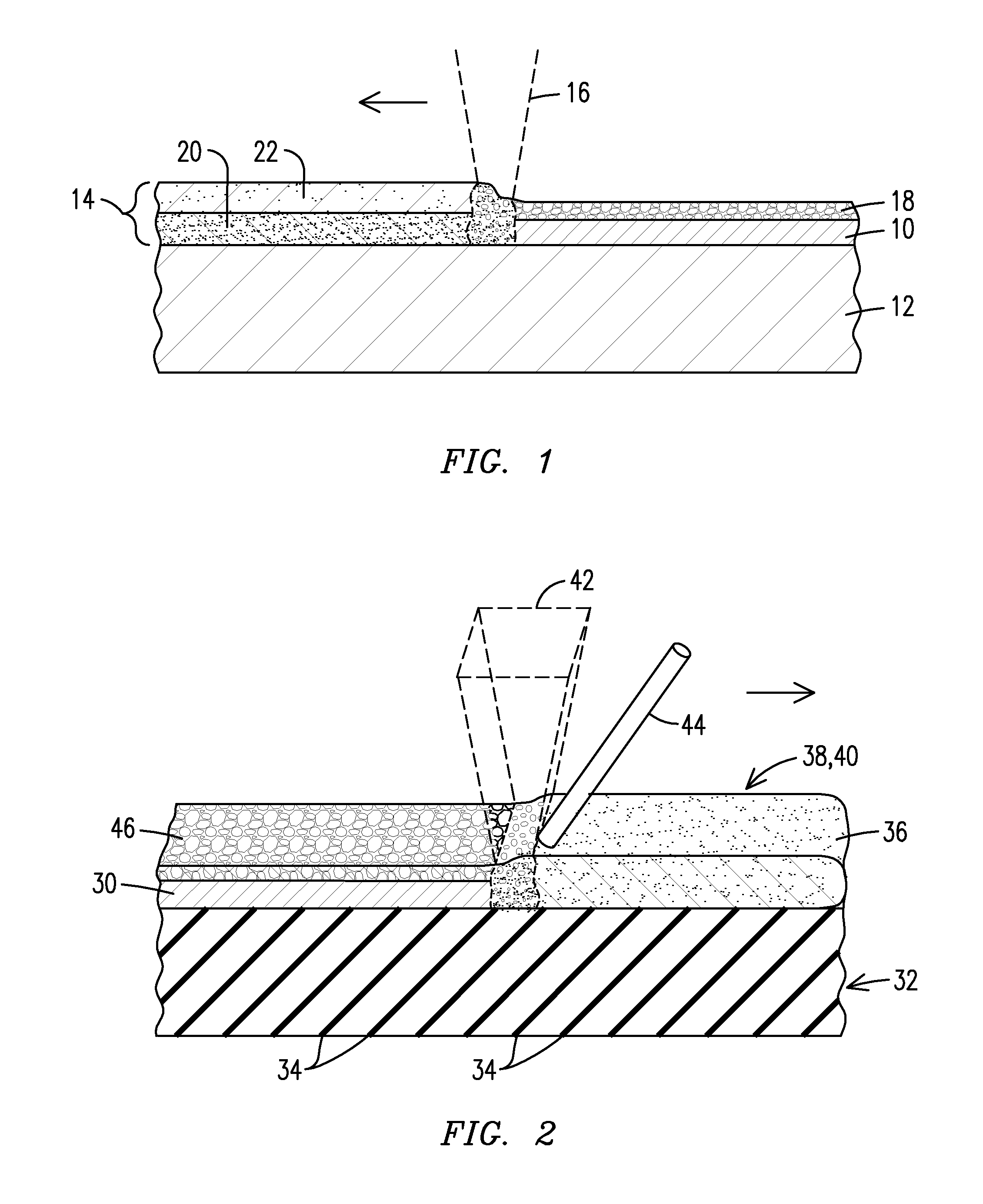
[0017]The present inventors have developed a flux material and a materials joining process that can be used successfully to join and / or to repair the most difficult to weld superalloy materials and other alloy materials. Embodiments of the inventive process advantageously apply a powdered flux material over a superalloy substrate during a laser melting and re-solidifying process. The powdered flux material is effective to provide beam energy transmission and selective trapping, impurity cleansing, atmospheric shielding, bead shaping, cooling temperature control, and alloy addition in order to accomplish crack-free joining of superalloy materials without the necessity for high temperature hot box welding or the use of a chill plate or the use of inert shielding gas or vacuum conditions.

[0018]FIG. 1 illustrates a process where a layer of cladding 10 of a superalloy material is being deposited onto a superalloy substrate material 12 at ambient room temperature without any preheating of...


PUM

PropertyMeasurementUnit
Fractionaaaaaaaaaa
Percent by massaaaaaaaaaa

Abstract

Flux compositions adapted for use in laser welding, repair and additive manufacturing applications. Flux compositions contain 5 to 60 percent by weight of an optically transmissive constituent, 10 to 70 percent by weight of a viscosity / fluidity enhancer, 0 to 40 percent by weight of a shielding agent, 5 to 30 percent by weight of a scavenging agent, and 0 to 7 percent by weight of a vectoring agent, in which the percentages are relative to a total weight of the flux composition. Also disclosed are processes involving melting of a superalloy material in the presence of a disclosed flux composition to form a melt pool covered by a layer of molten slag, and allowing the melt pool and the molten slag to cool and solidify to form a superalloy layer covered by a layer of solid slag.

Description

[0001]This application claims benefit of the 29 Jul. 2013 filing date of U.S. provisional application No. 61 / 859,317 (attorney docket number 2013P12177US), the entire contents of which are hereby incorporated by reference.FIELD OF THE INVENTION[0002]This invention relates generally to the field of metals joining, and more particularly to the welding, repair and additive manufacturing of superalloy materials using a laser energy heat source, and to a flux material for laser welding.BACKGROUND OF THE INVENTION[0003]Welding processes vary considerably depending upon the type of material being welded. Some materials are more easily welded under a variety of conditions, while other materials require special processes in order to achieve a structurally sound joint without degrading the surrounding substrate material.[0004]Common arc welding generally utilizes a consumable electrode as the feed material. In order to provide protection from the atmosphere for the molten material in the weld...

Claims


Application Information

Patent Timeline
IPC IPC(8): B23K35/34B23K25/00B23K35/36B23K26/32
CPCB23K35/34B23K26/3206B23K25/00B23K35/361B23K35/3602B23K35/3607B23K35/3605B23K35/3601B23K35/327B23K35/362B23K26/34B23K26/342B23K26/346
Inventor BRUCK, GERALD J.KAMEL, AHMED
Owner SIEMENS ENERGY INC
Learn More