Radiation detector

a detector and radiation technology, applied in the field of radiation detectors, can solve the problem that the depth resolution of the scintillator is not sufficient in any related art, and achieve the effect of simple structure and higher position resolution

Inactive Publication Date: 2015-01-29
WASEDA UNIV +1
View PDF2 Cites 31 Cited by
  • Summary
  • Abstract
  • Description
  • Claims
  • Application Information

AI Technical Summary

Benefits of technology

[0021]An object of the present invention is to provide a radiation detector which realizes a higher position resolution in a scintillator depth direction than in the related art, with a relatively simple structure.
[0023]According to the present invention, it is possible to provide a radiation detector which realizes a higher position resolution in a scintillator depth direction than in the related art, with a relatively simple structure.

Problems solved by technology

A position resolution in a scintillator depth direction is not sufficient in any related art.
In addition, many problems to be solved, such as assembly being difficult due to a complex structure and a waveform acquisition circuit or a reading circuit being complex, still remain in realizing mass production as a device.

Method used


Image

  • Radiation detector
  • Radiation detector
  • Radiation detector

Examples


example 1

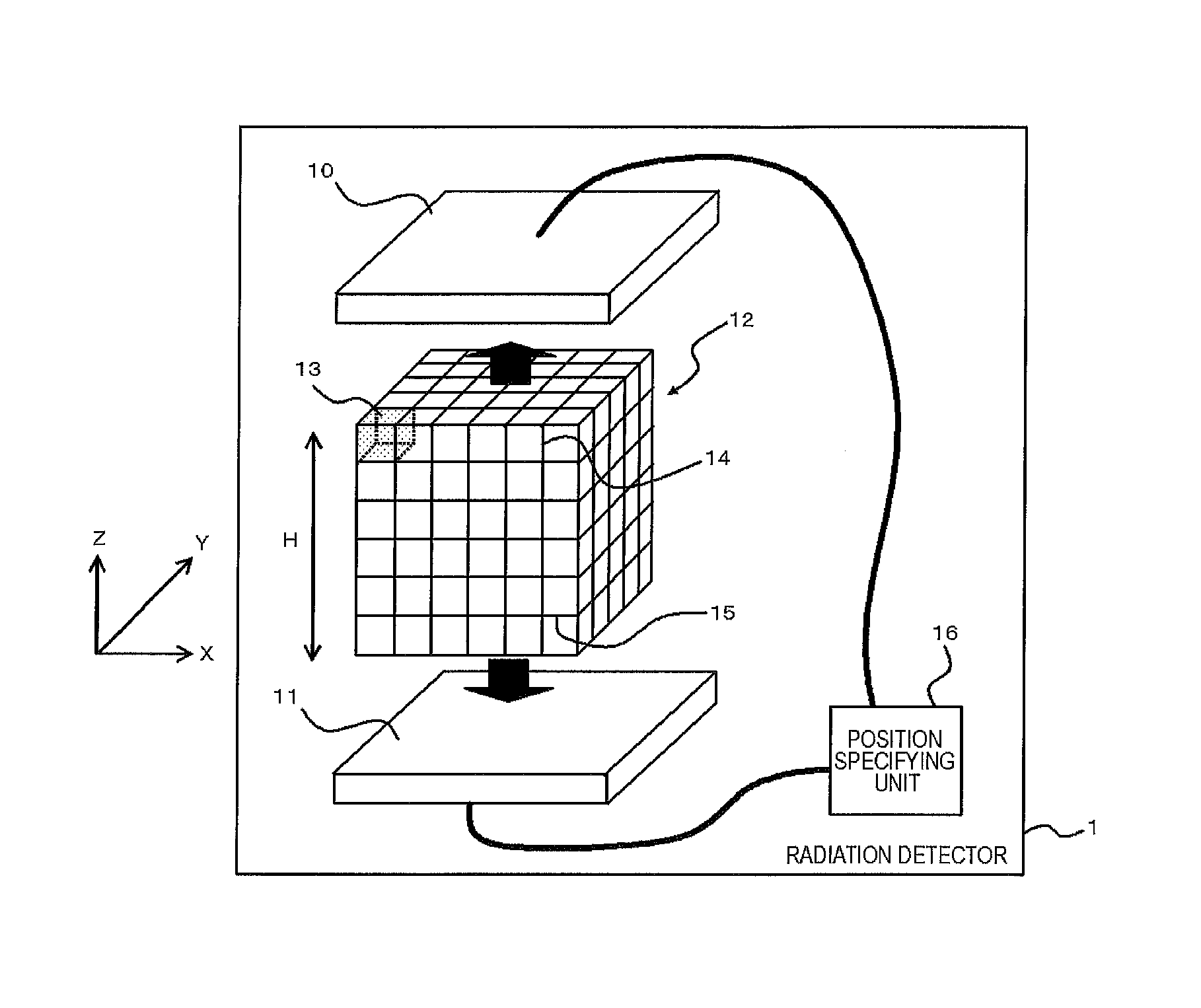
[0082]In Example 1, as illustrated in FIG. 5, a radiation detector was manufactured in which the scintillator blocks 13 are stacked in the z direction. FIG. 5 is a schematic diagram of a cross-section of the radiation detector of Example 1.

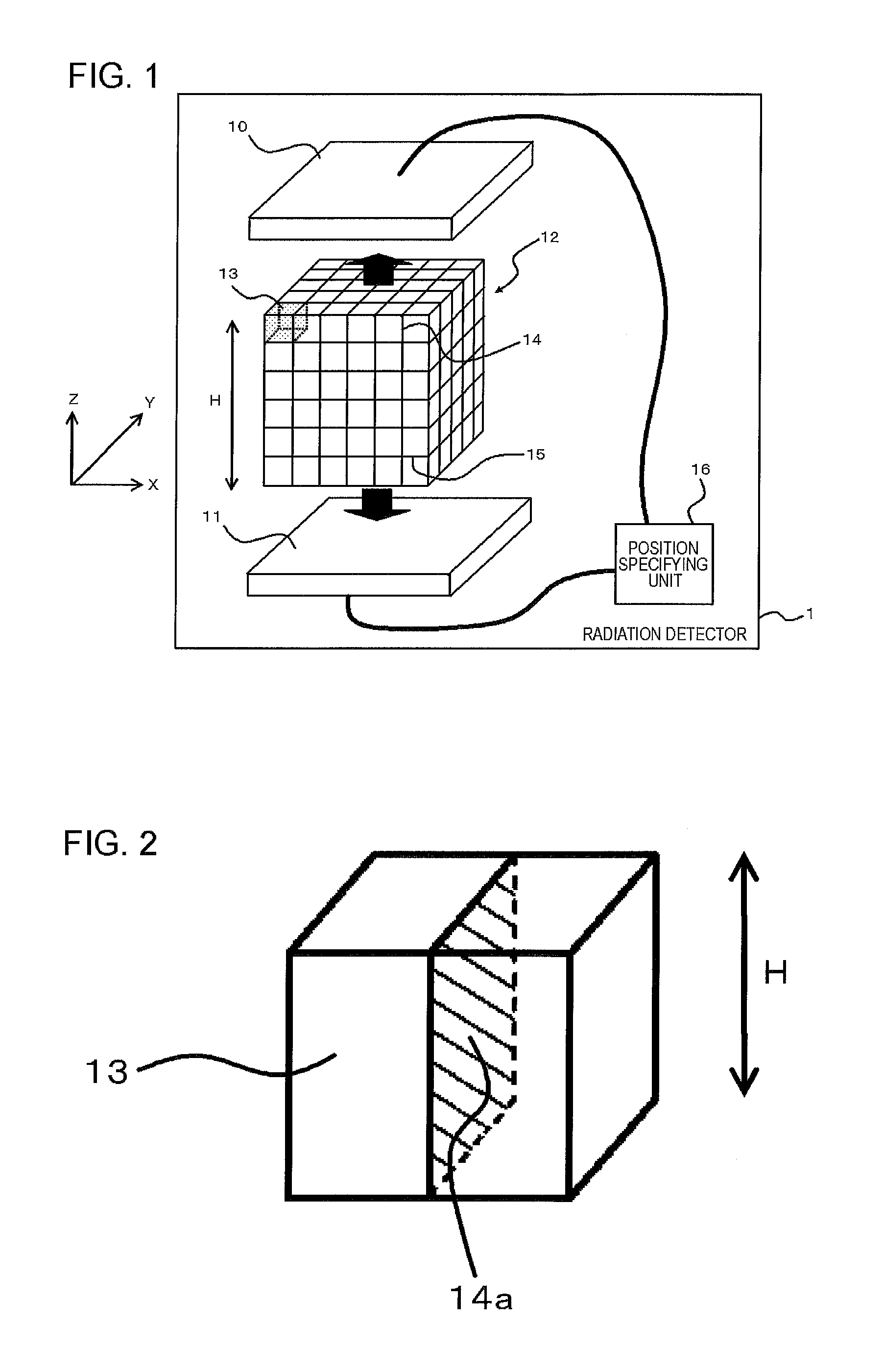
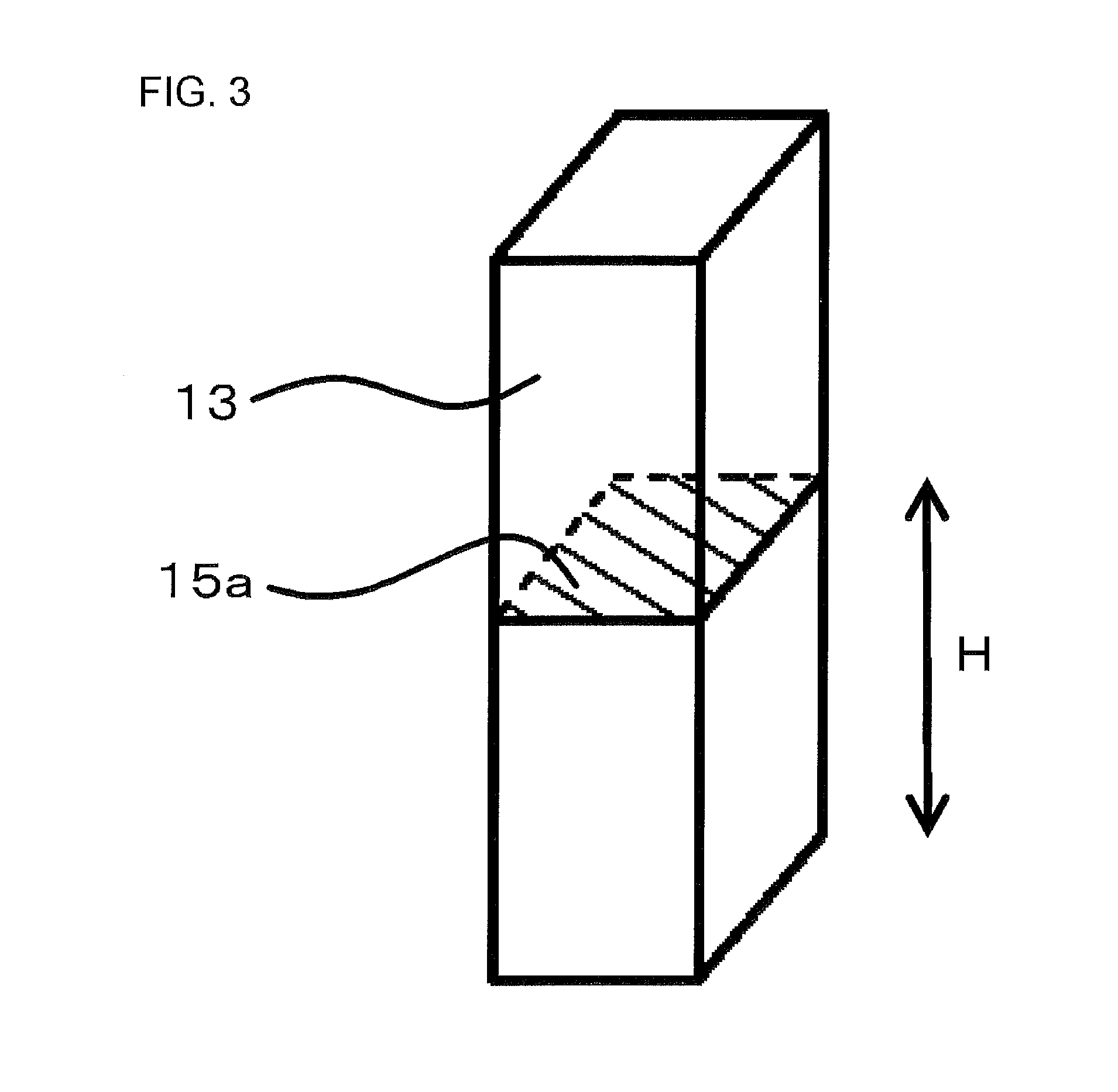
[0083]The scintillator block 13 is a Ce:GAGG (Ce:Gd3Al2Ga3O12) (hereinafter, referred to as “Ce:GAGG”) crystal doped with cerium. A shape thereof was a shape of a cube which is 3 mm long, 3 mm wide, and 3 mm high.

[0084]Five scintillator blocks 13 were stacked with air layers (interposed layers 15) having a thickness of 10 μm interposed therebetween in the z direction. Next, the entire outer circumference of the side surfaces of the stacked body was covered by a fluororesin film (light blocking layer 14) with a thickness of 1 mm. In addition, silicon photomultipliers (light receiving elements 10 and 11) having a light receiving surface of 3 mm×3 mm were optically coupled to both ends of the stacked body in the z direction, thereby manufacturing the...

example 2

[0087]In Example 2, as illustrated in FIG. 7, a radiation detector was manufactured in which the scintillator blocks 13 were arranged in a three-dimensional manner (4×4×4). FIG. 7 is a schematic diagram of a cross-section of the radiation detector of Example 2.

[0088]The scintillator block 13 is a Ce:GAGG crystal. A shape thereof was a shape of a cube which is 3 mm long, 3 mm wide, and 3 mm high. The interposed layer 15 was an air layer with a thickness of 10 μm. The light blocking layer 14 was 0.2 mm thick, and contained barium sulfate. In addition, the light blocking layers 14 were provided on, among the scintillator block boundary surfaces, all boundary surfaces which extend in a direction parallel to the height direction H (the z direction in FIG. 7) of the three-dimensional stacked scintillator 12 (prism). In addition, the entire outer circumference of the side surfaces of the three-dimensional stacked scintillator 12 obtained through three-dimensional arrangement (4×4×4) of the...

example 3

[0090]In Example 3, a LYSO (Ce:(Lu,Y)2SiO5) (hereinafter, referred to as “Ce:LYSO”) crystal doped with cerium was used as the scintillator block 13. Other configurations are the same as those of the radiation detector of Example 1.

[0091]The radiation detector was irradiated with gamma rays of 662 keV from a cesium 137 radiation source, and a voltage pulse signal output from each of the silicon photomultipliers was analyzed by using Equation (1), thereby obtaining a position resolution spectrum illustrated in FIG. 9. A position resolution in the z direction had the performance of discriminating a position of the scintillator block having a thickness of 3 mm with a resolution of FWHM=0.4 mm, and an energy resolution was 11.3%.

[0092]As described above, it can be seen that the radiation detector of the present embodiment which is obtained by arranging a plurality of radiation detectors of Example 3 in parallel has a good position resolution in a depth direction (z direction).


PUM


Abstract

A radiation detector (1) includes a three-dimensional stacked scintillator (12) that includes a plurality of scintillator blocks (13) arranged in a matrix in a three-dimensional manner so as to form a prism, in which interposed layers (15) which have a refractive index different from a refractive index of the scintillator blocks (13) and / or have a characteristic of absorbing or scattering some of light emitted by the scintillator blocks are disposed, out of boundary surfaces between the plurality of scintillator blocks (13), on the boundary surfaces extending in a direction perpendicular to a height direction H of the prism, and light blocking layers (14) which block transmission of light emitted by the scintillator are disposed on at least some of the boundary surfaces extending in a direction parallel to the height direction of the prism.

Description

TECHNICAL FIELD[0001]The present invention relates to a radiation detector.BACKGROUND ART[0002]A radiation detector is used in nuclear medicine imaging apparatuses such as, for example, positron emission tomography (PET), single photon emission computed tomography (SPECT), and a gamma camera. The nuclear medicine apparatuses are apparatuses which use a property in which annihilation gamma rays are emitted when a positron radioactive isotope (RI) labeling agent is administered to a subject, and use a radiation detector so as to detect annihilation gamma rays, thereby obtaining an RI distribution image of the subject.[0003]Here, in the radiation detector used in the foregoing application, a technique for detecting a light emitting position in a depth direction (length direction) of the radiation detector is desired in order to realize further improvement in a spatial resolution.[0004]Patent Document 1 discloses the following three-dimensional radiation incidence position detector. The...

Claims


Application Information

Patent Timeline
Patent Type & Authority Applications(United States)
IPC IPC(8): G01T1/202G01T1/29G01T1/164
CPCG01T1/202G01T1/2985G01T1/1642G01T1/1644G01T1/2008G01T1/2002
Inventor KATAOKA, JUNKISHIMOTO, AYAKAMADA, KEI
Owner WASEDA UNIV
Why Eureka
Try Eureka