
Transmitter and method with RF power amplifier having predistorted bias

a technology of rf power amplifier and predistorted bias, which is applied in the direction of differential amplifier, amplifier with semiconductor device/discharge tube, amplifier details, etc., can solve the problems of transmitters that violate regulatory requirements, all linear rf power amplifiers fail to meet, distortion and spectral regrowth,

Inactive Publication Date: 2015-01-29
CRESTCOM INC
View PDF3 Cites 32 Cited by
  • Summary
  • Abstract
  • Description
  • Claims
  • Application Information

AI Technical Summary

Benefits of technology

The present invention relates to improving the linearity and power-added efficiency (PAE) of RF transmitters. More specifically, it addresses the issue of unwanted intermodulation and spectral regrowth caused by sub-RF distortion signals generated by RF power amplifiers. The invention proposes a solution to stabilize the RF power amplifier biasing signals to improve linearity and PAE. It also addresses the issue of envelope tracking (ET) and envelope elimination and restoration (EER) techniques used for achieving PAE improvements. Overall, the invention aims to provide a more efficient and linear RF transmitter for improved performance and reliability.

Problems solved by technology

While perfect linearity is a goal for any linear RF power amplifier, all linear RF power amplifiers invariably fail to meet it.
The degree to which the goal of perfect linearity is missed leads to unwanted intermodulation, distortion, and spectral regrowth.
Even small amounts of spectral regrowth can cause the transmitter to violate regulatory requirements.
An amplifier that has low PAE wastes power, which is undesirable in any transmitter, but particularly undesirable in battery-powered transmitters because it necessitates the use of undesirably large batteries and / or undesirably frequent recharges.
Those who design RF transmitters understand that different RF power amplifier limitations lead, directly and indirectly, to different types of nonlinearities.
One of these nonlinearities results indirectly from an unwanted amplifier-generated low-frequency distortion signal referred to as a video signal or a baseband signal.
In particular, RF power amplifiers tend to generate unwanted harmonics of the fundamental RF communication signal being amplified along with the desired amplified fundamental RF communication signal.
But the even harmonics have sub-RF byproducts below the fundamental in frequency, extending upward from zero Hz, and these amplifier-generated, sub-RF byproducts represent one form of troublesome distortion.
In some RF power amplifiers additional mechanisms may be present to generate other forms of troublesome sub-RF distortion.
While these sub-RF distortion signals are not broadcast from the transmitter, they may nevertheless impede efforts to improve linearity and PAE.
The amplifier-generated sub-RF distortion signal causes a time-varying voltage to develop across the biasing network, which causes a corresponding and unwanted time-varying voltage modulation of the desired bias voltage applied across conduction nodes of the RF amplifying device.
The intentionally applied, time-varying bias signal causes both a wanted time-varying voltage modulation of the bias voltage and an unwanted distortion modulation which occupies substantially the same or a greater bandwidth as the time-varying bias signal.
The sub-RF distortion signals can lead to unwanted intermodulations between the sub-RF distortion signals and the RF fundamental signal.
This type of RF distortion signal is undesirable because it reduces the signal-to-noise ratio of the transmitted RF signal.
But it is highly undesirable due to the spectral regrowth which often must be corrected in order for the transmitter to comply with its spectral mask.
Thus, the sub-RF distortion signals cause the RF amplifying device's bias signal to be less stable than desired.
Unfortunately, this technique does not work well for wide bandwidth signals.
For wide bandwidth communication signals it becomes increasingly difficult to configure a biasing network to exhibit adequately low impedance throughout a wide sub-RF distortion signal bandwidth yet exhibit adequately high impedance at the fundamental RF frequency.
And, the inclusion of resonant notches in the biasing network is undesirable because it worsens another type of nonlinearity, referred to as “memory effects”.
The memory-effect nonlinearities are particularly undesirable because they are difficult to compensate using predistortion techniques which require reasonable computational abilities and consume little power.
But the bias signal fed to the amplifying device remains less stable in the sub-RF distortion bandwidth than desired.
Unfortunately, this technique wastes power and reduces PAE.
Unfortunately, the sub-RF distortion signals are believed to add a component of bias variation which prevents envelope tracking techniques from achieving desired levels of improvement in PAE.

Method used


Image

  • Transmitter and method with RF power amplifier having predistorted bias
  • Transmitter and method with RF power amplifier having predistorted bias
  • Transmitter and method with RF power amplifier having predistorted bias

Examples


Embodiment Construction

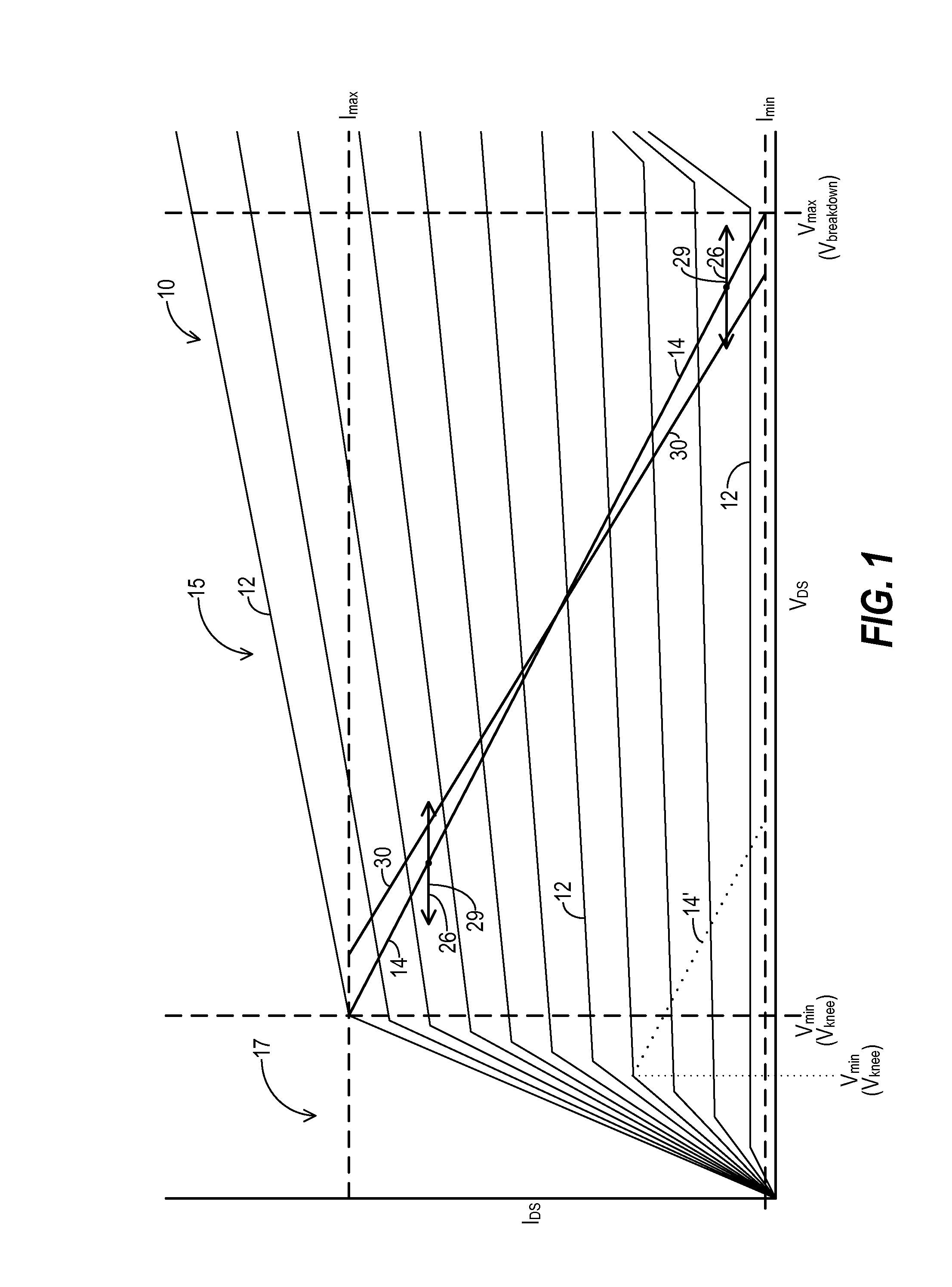
[0022]FIG. 1 shows a chart depicting a representative family 10 of transfer curves 12 for a representative RF amplifying device (not shown) using field effect transistor (FET) nomenclature. The basic relationships shown in FIG. 1 apply to other types of RF amplifying devices as well. Current IDS flowing through a conduction channel of the RF amplifying device between its drain and source conduction nodes is represented along the vertical axis, and voltage VDS across the drain and source conduction nodes is represented along the horizontal axis. A different transfer curve 12 is presented for each of several different levels for an input signal VGS presented to the RF amplifying device across gate and source nodes.

[0023]An optimal load line 14 extends between the knee voltage (Vknee) for VDS at a high level of input signal VGS, and the breakdown voltage (Vbreakdown) for VDS at a lower level of the input signal VGS. Optimal load line 14 is defined by amplifier characteristics in combin...


PUM


Abstract

A transmitter (32) generates a time-varying stabilized bias signal (82) from which sub-RF distortion signals (26, 29) have been cancelled. The distortion signals (26, 29) are byproducts of imperfect amplification and of biasing networks. An envelope amplifier (84) includes a high bandwidth differential input, linear, bias signal amplifier (120) and a low bandwidth switching amplifier (122) coupled together to achieve both a high bandwidth and high efficiency. A control loop (154) feeds a portion of the voltage V(t) from a conduction node (146) of the RF power amplifier (36) to one of the differential inputs of the linear bias signal amplifier (120), while a bias control signal (92) drives the other differential input. The portion of voltage V(t) fed to bias signal amplifier (120) is a low power portion from which the RF portion has been removed. A bias signal (128) may be predistorted to cancel distortion signals (26, 29).

Description

TECHNICAL FIELD OF THE INVENTION[0001]The present invention relates generally to the field of radio-frequency (RF) communication systems. Specifically, the present invention relates to RF transmitters that stabilize RF power amplifier biasing signals to improve transmitter linearity and power-added efficiency.BACKGROUND OF THE INVENTION[0002]An RF power amplifier provides the final stage of amplification for a communication signal that has been modulated and converted into an RF signal. Often that RF signal exhibits frequencies in a predetermined RF frequency band licensed by a regulatory agency for a particular use. The RF power amplifier boosts the power of this RF communication signal to a level sufficient so that the signal, when it propagates to an antenna, will be broadcast in such a manner that it will meet the communication goals of the RF transmitter.[0003]Many popular modern modulation techniques, such as CDMA, QAM, OFDM, and the like, require the RF power amplifier to per...

Claims


Application Information

Patent Timeline
IPC IPC(8): H03F1/32H04B1/62H03F3/193H03F3/21H03F3/45
CPCH03F1/3247H03F3/193H04B1/62H03F3/45179H03F3/21H03F1/0222H03F3/2171H03F3/245H03F3/45475H03F2200/432
Inventor MCCALLISTER, RONALD DUANE
Owner CRESTCOM INC
Features
  • Generate Ideas
  • Intellectual Property
  • Life Sciences
  • Materials
  • Tech Scout
  • Unparalleled Data Quality
  • Higher Quality Content
  • 60% Fewer Hallucinations
Learn More