Vapor deposition mask, method for producing vapor deposition mask device and method for producing organic semiconductor element

a technology of vapor deposition mask and vapor deposition mask, which is applied in vacuum evaporation coating, chemistry apparatus and processes, coatings, etc., can solve the problems of easy distortion of slits, slit length, and obstacle to enhancement of definition or upsizing of products, so as to improve definition and improve precision , the effect of reducing weigh

Active Publication Date: 2015-02-05
DAI NIPPON PRINTING CO LTD
View PDF2 Cites 69 Cited by
  • Summary
  • Abstract
  • Description
  • Claims
  • Application Information

AI Technical Summary

Benefits of technology

[0013]According to the vapor deposition mask of the present invention, even when the size is increased, both enhancement in definition and reduction in weight can be satisfied. Further, according to the method for producing a vapor deposition mask device of the present invention, the above described vapor deposition mask can be aligned to the frame with high precision, in addition to the effect of the above described vapor deposition mask. Further, according to the method for producing an organic semiconductor element of the present invention, an organic semiconductor element can be produced with high precision.

Problems solved by technology

While in the case of using the vapor deposition mask, the vapor deposition mask is placed on a substrate front surface that should be subjected to vapor deposition and is held by using a magnet from a back surface, the rigidity of the slits is extremely small, and therefore, distortion easily occurs to the slits when the vapor deposition mask is held on the substrate front surface, which becomes an obstacle to enhancement in definition or upsizing of the products in which the slit lengths are large.
However, with the present metal processing technique, it is difficult to form slits in a large metal plate with high precision, and even if distortion in slit portions can be prevented by the method proposed in the above described Patent Literature 1 or the like, the method or the like cannot respond to enhancement in definition of the slits.
Further, in the case of use of a vapor deposition mask composed of only a metal, the mass thereof also increases with upsizing, and the total mass including a frame also increases, which becomes a hindrance to handling.

Method used


Image

  • Vapor deposition mask, method for producing vapor deposition mask device and method for producing organic semiconductor element
  • Vapor deposition mask, method for producing vapor deposition mask device and method for producing organic semiconductor element
  • Vapor deposition mask, method for producing vapor deposition mask device and method for producing organic semiconductor element

Examples


Embodiment Construction

[0024]Hereinafter, the vapor deposition mask 100 of the present invention will be described specifically with use of the drawings.

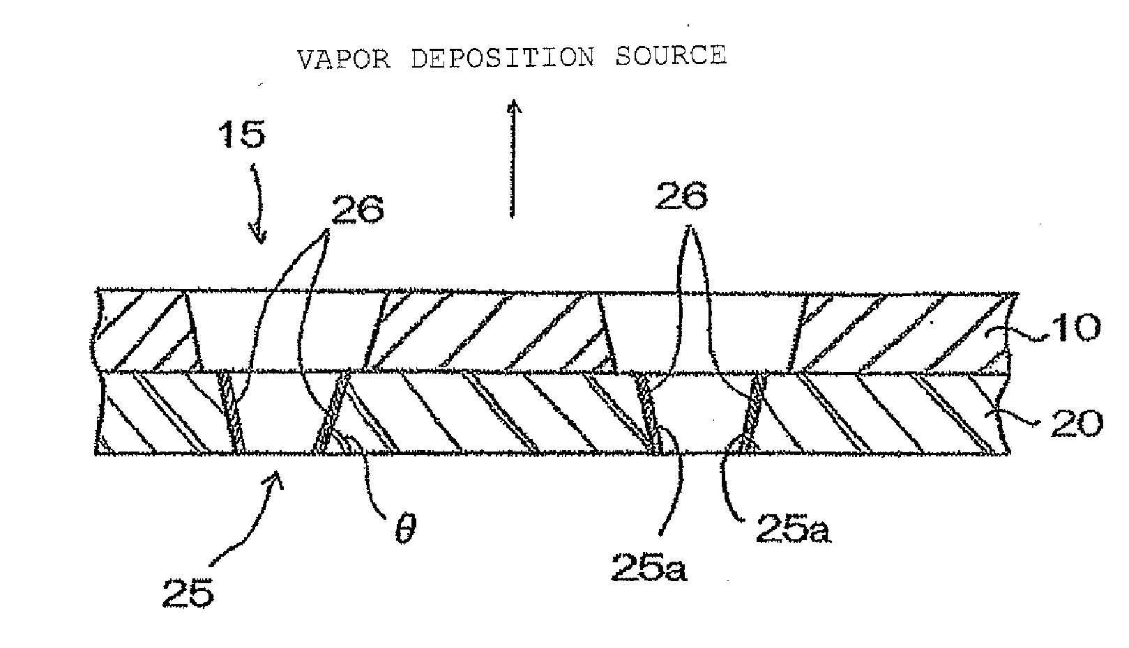
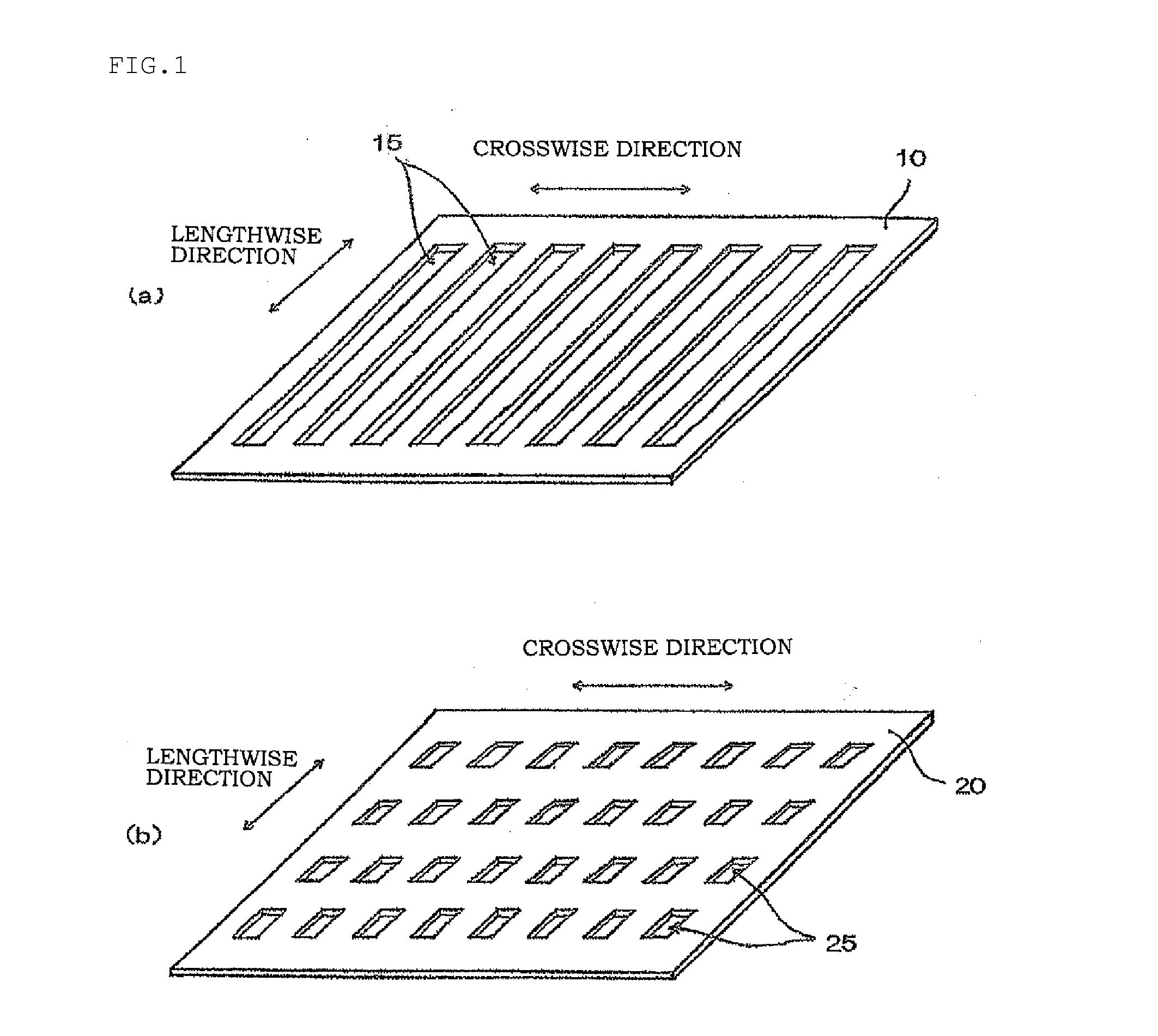
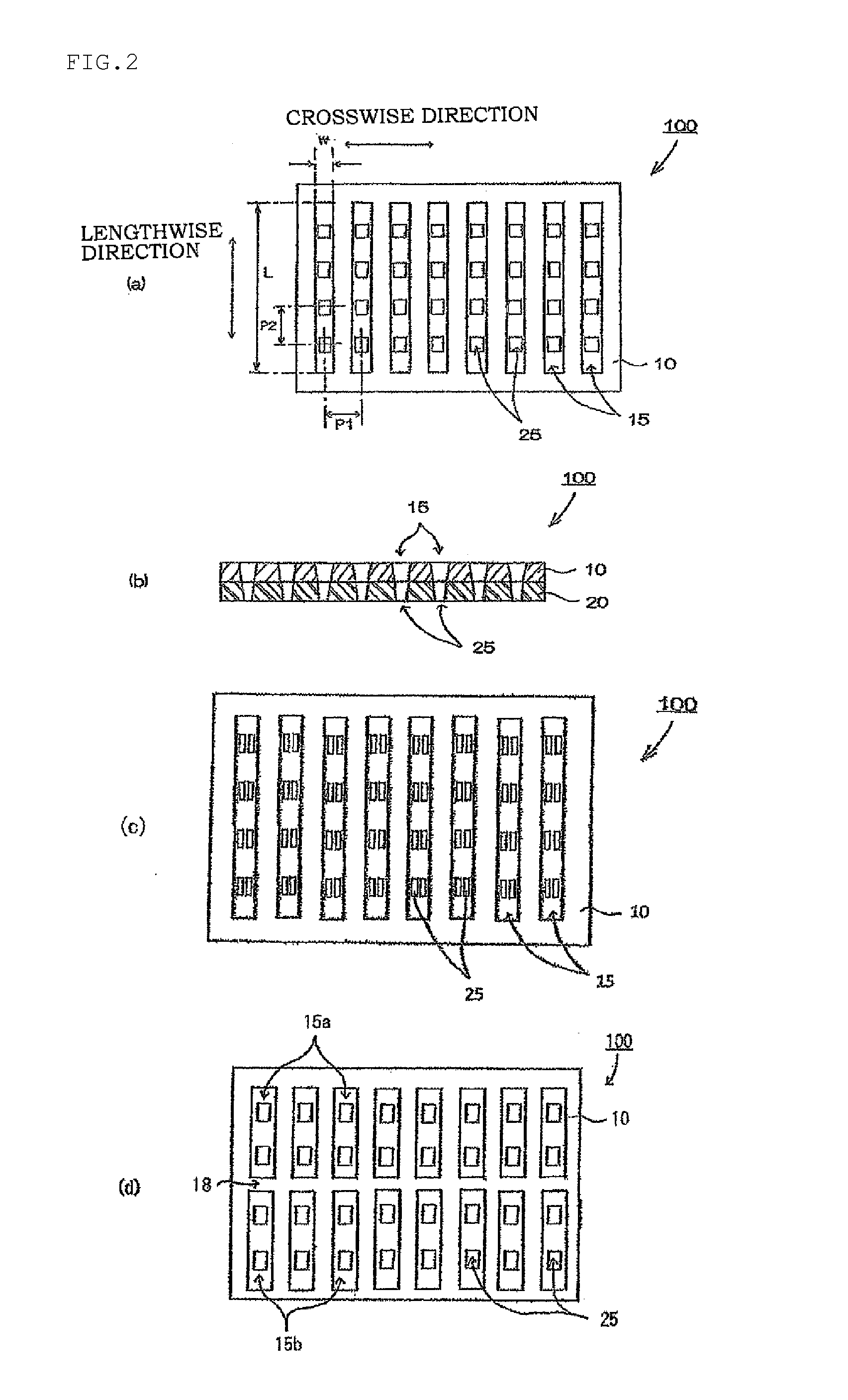
[0025]FIG. 1 (a) is a schematic perspective view of a metal mask configuring a vapor deposition mask showing one example of the present invention, and FIG. 1 (b) is a schematic perspective view of a resin mask configuring the vapor deposition mask showing one example of the present invention. FIG. 2 (a) is a front view of the vapor deposition mask showing one example of the present invention, seen from a metal mask side, and FIG. 2 (b) is a schematic sectional view showing the vapor deposition mask showing one example of the present invention. FIG. 3 is an enlarged sectional view of the vapor deposition mask 100 of the present invention. Note that in each of FIGS. 1 to 3, in order to emphasize slits provided in the metal mask and openings provided in the vapor deposition mask, the ratios thereof to the whole body are illustrated to be large.

[0026]In the v...


PUM

PropertyMeasurementUnit
thicknessaaaaaaaaaa
humidity absorptionaaaaaaaaaa
thicknessaaaaaaaaaa

Abstract

A method for producing a vapor deposition mask capable of satisfying both enhancement in definition and reduction in weight even when a size is increased, a method for producing a vapor deposition mask device capable of aligning the vapor deposition mask to a frame with high precision, and a method for producing an organic semiconductor element capable of producing an organic semiconductor element with high definition are provided. A metal mask provided with a slit, and a resin mask that is positioned on a front surface of the metal mask and has openings corresponding to a pattern to be produced by vapor deposition arranged by lengthwise and crosswise in a plurality of rows, are stacked.

Description

TECHNICAL FIELD[0001]The present invention relates to a vapor deposition mask, a method for producing a vapor deposition mask device and a method for producing an organic semiconductor element.BACKGROUND ART[0002]Conventionally, in production of an organic EL element, a vapor deposition mask that is composed of a metal formed by a number of microscopic slits being arranged in parallel with one another at microscopic spaces in a region that should be subjected to vapor deposition, for example, has been used in formation of an organic layer of an organic EL element or a cathode electrode. While in the case of using the vapor deposition mask, the vapor deposition mask is placed on a substrate front surface that should be subjected to vapor deposition and is held by using a magnet from a back surface, the rigidity of the slits is extremely small, and therefore, distortion easily occurs to the slits when the vapor deposition mask is held on the substrate front surface, which becomes an o...

Claims


Application Information

Patent Timeline
Patent Type & Authority Applications(United States)
IPC IPC(8): B05C21/00H01L51/56H01L51/00B32B37/18B32B38/00
CPCB05C21/005B32B37/182B32B38/0008B32B2398/00H01L51/56B32B2310/0843B32B2311/00H01L51/0011C23C14/042C23C14/24H05B33/10H10K71/166H10K50/00H10K71/00C23F1/02G03F7/20C23C14/04H01L21/027H10K50/11B05B12/20
Inventor HIROBE, YOSHINORIMATSUMOTO, YUTAKAUSHIKUSA, MASATOTAKEDA, TOSHIHIKONISHIMURA, HIROYUKIOBATA, KATSUNARITAKEKOSHI, TAKASHI
Owner DAI NIPPON PRINTING CO LTD
Why Eureka
Try Eureka