
Integration of phase change materials inside evacuated tube solar collector for storage and transfer of thermal energy

a solar collector and phase change technology, applied in solar heat storage, solar heat reduction, lighting and heating apparatus, etc., can solve the problems of increasing the thermal conductivity of the pcm, not all pcms are ideal for our novel idea, and low thermal conductivity

Inactive Publication Date: 2015-02-12
SOLARNO +1
View PDF1 Cites 27 Cited by
  • Summary
  • Abstract
  • Description
  • Claims
  • Application Information

AI Technical Summary

Benefits of technology

The invention is a method to store heat inside a solar collector for later use. The method involves using a heat pipe and a phase change material to connect the heat pipe to the solar collector. The phase change material can accumulate heat from solar radiation and release it later by controlling the flow of water or using an anti-freeze fluid. This allows for more efficient use of solar energy.

Problems solved by technology

One of the challenges in the application of phase change materials is increasing their thermal conductivity while maintaining their high latent capacity.
Although PCMs are good candidates for storage applications, not all PCMs are ideal for our novel idea.
The PCM to be used in the evacuated tube solar collectors should have a high melting temperature, between 100° C. and 180° C. PCMs with high melting temperature usually have low thermal conductivity, high cost, subcooling, and poor stability during the temperature cycling; the number of suitable phase change materials which are suggested in the literature is very limited.

Method used


Image

  • Integration of phase change materials inside evacuated tube solar collector for storage and transfer of thermal energy
  • Integration of phase change materials inside evacuated tube solar collector for storage and transfer of thermal energy
  • Integration of phase change materials inside evacuated tube solar collector for storage and transfer of thermal energy

Examples


example 1

Performance of Evacuated Tube Collector Systems Filled with Phase Change Materials

[0033]In order to evaluate the performance of phase change material inside evacuated tube collector, field test on 0.5 meter collectors were carried out. FIG. 7 shows curves of the temperature inside the tube in three different cases. Two paraffin based PCM materials with different working temperatures (56° C. and 73° C.) were added inside the tube collector are compared to a standard tube collector. Also, erythritol was used for comparison with paraffin PCM. The temperature of metal fins of ETC was measured after exposure to sun for 3 hours and during the cool down in the shade. A small water tank (600 ml) was placed on top of heat pipe. In the case of the 56° C. PCM filled tube; we observe a significantly faster cooling rate. In the case of paraffin 73° C. the temperature inside the tube remains higher that paraffin 56° C. In FIG. 8 we show the recorded temperatures inside small water tank on the top...

example 2

On-Demand Operation of Evacuated Tube Collector SWH System Filled with Phase Change Material

[0035]In FIG. 10 we report results recorded during cool down of systems. Initially, both solar collectors were kept in stagnation mode, i.e. without a water flow through heat exchanger. A few seconds before systems being covered from sunlight, water flow started with the rate of at 0.2 GPM.

[0036]We observe the temperature inside evacuated tubes to be significantly higher compared to operation in normal mode, since no heat transfer to water is possible. We can assume that phase change of paraffin has occurred for the majority of the material since the temperature inside the tubes with paraffin has exceeded 73° C. We observe the fast cool down of standard evacuated tube (∘) and the delayed cool down of PCM tubes (). While systems are stagnated, the majority of absorbed energy is accumulated in PCM materials. Once the water flow is started, the energy can be transferred to water through the hea...

example 3

Operation of ETC Solar Collector Assemblies with PCM

[0038]Two systems (typical ETC system and PCM integrated system) were operated daily under similar conditions. The solar water heaters were operated in two different modes, first in normal operation the water is circulated between the manifold of the collector at a constant flow rate and the water tank. Second, in stagnation mode, no water flow was initiated through the manifold for an extended time and the pump was not started until PCM in both systems was melted and collectors have been covered completely from sun. The temperatures of water in the storage tank of a typical solar water system and a PCM integrated systems are shown in FIG. 12 for normal operational mode. In all cases the temperature appears peak at time the systems are covered, where the temperature in tank of system without PCM cools down rapidly. In contrast, the tank of paraffin filled system shows a slower cooling rate and the significant heat loss from uninsul...


PUM


Abstract

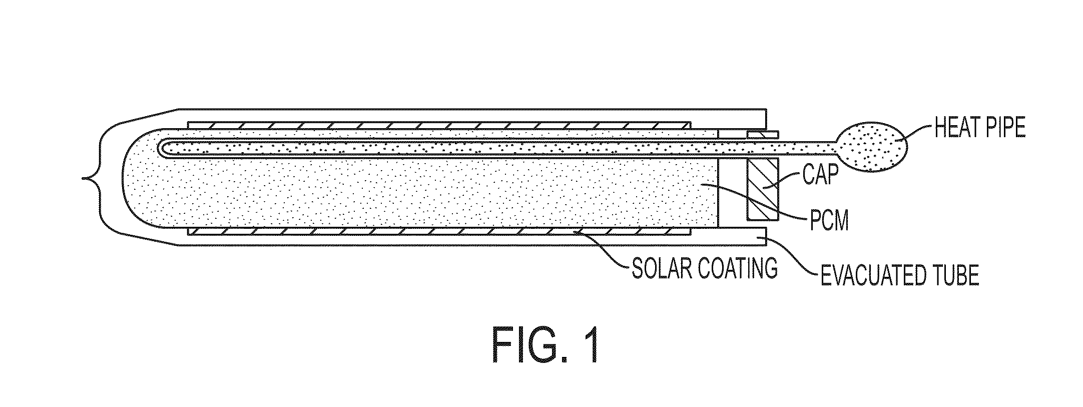
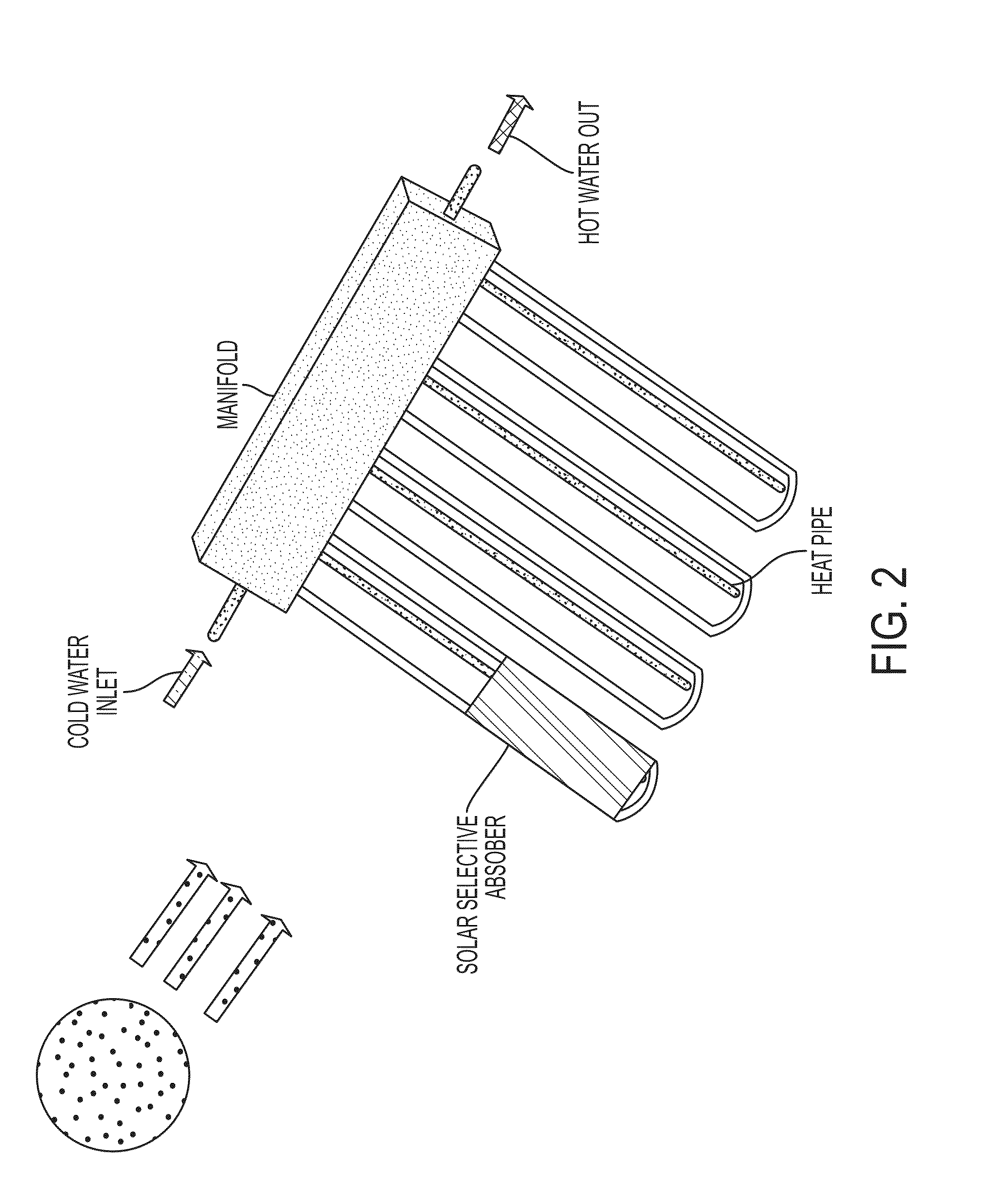
An objective of the invention is to design and develop an effective method to collect and store heat in a solar collector for delayed release. An embodiment of the invention is directed to an evacuated tube collector, where PCM is placed directly inside the void space of the collector tube, next to the heat pipe. The heat pipe is located with phase change material (PCM) in such a way that its thermal connection with the heat pipe can be switched “ON” to start heat transfer from PCM or “OFF” to keep latent heat stored in PCM for delayed usage. In additional, flow of heat exchange fluid through the manifold can enable release of stored heat of PCM to storage tank. Delayed release of accumulated heat in PCM enables added functionality of on-demand operation of SWH.

Description

CROSS-REFERENCES TO RELATED APPLICATIONS[0001]This application claims the benefit under 35 U.S.C. §119(e) of U.S. Provisional Patent Application No. 61 / 863,797 filed Aug. 8, 2013, which is incorporated herein by reference in its entirety as if fully set forth herein.STATEMENT REGARDING FEDERALLY-SPONSORED RESEARCH OR DEVELOPMENT[0002]This invention was made with government support under DOE Phase I STTR Grant No. 87938T12-I awarded by the Department of Energy. The government has certain rights in the invention.BACKGROUND OF THE INVENTION[0003]1. Field of the Invention[0004]This invention relates to solar heating of water for industrial and residential applications, and more specifically it relates to evacuated tube collector (ETC) solar water heaters, which use the heat pipe for effective and high temperature water heating and describes a new method to integrate phase change material (PCM) inside the inner space of ETC, in order to store heat and transfer effectively and use it with...

Claims


Application Information

Patent Timeline
IPC IPC(8): F24J2/34
CPCF24J2/34C09K5/063C09K5/10F28D20/02F28F13/00F24S10/45F24S10/95F24S60/10Y02E10/44Y02E60/14Y02E70/30
Inventor ZAKHIDOV, ANVAR A.POZDIN, VLADIMIR A.HASSANIPOUR, FATEMEHDARMANYAN, SERGEYPAPADIMITRATOS, ALEXIOS
Owner SOLARNO
Learn More