Ultraviolet laser sterilization system

Active Publication Date: 2015-02-19
NAT CHENG KUNG UNIV
View PDF9 Cites 7 Cited by
  • Summary
  • Abstract
  • Description
  • Claims
  • Application Information

AI Technical Summary

Benefits of technology

[0008]In view of the above-mentioned problems, the object of the present invention is to provide an ultraviolet laser sterilization system, especially referring to an ultraviolet laser light scanner for generating and receiving ultraviolet las

Problems solved by technology

Therefore, by using the ultraviolet laser sterilization sys

Method used


Image

  • Ultraviolet laser sterilization system
  • Ultraviolet laser sterilization system

Examples


Embodiment Construction

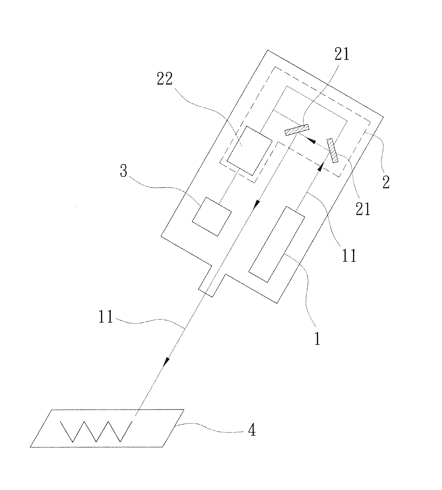
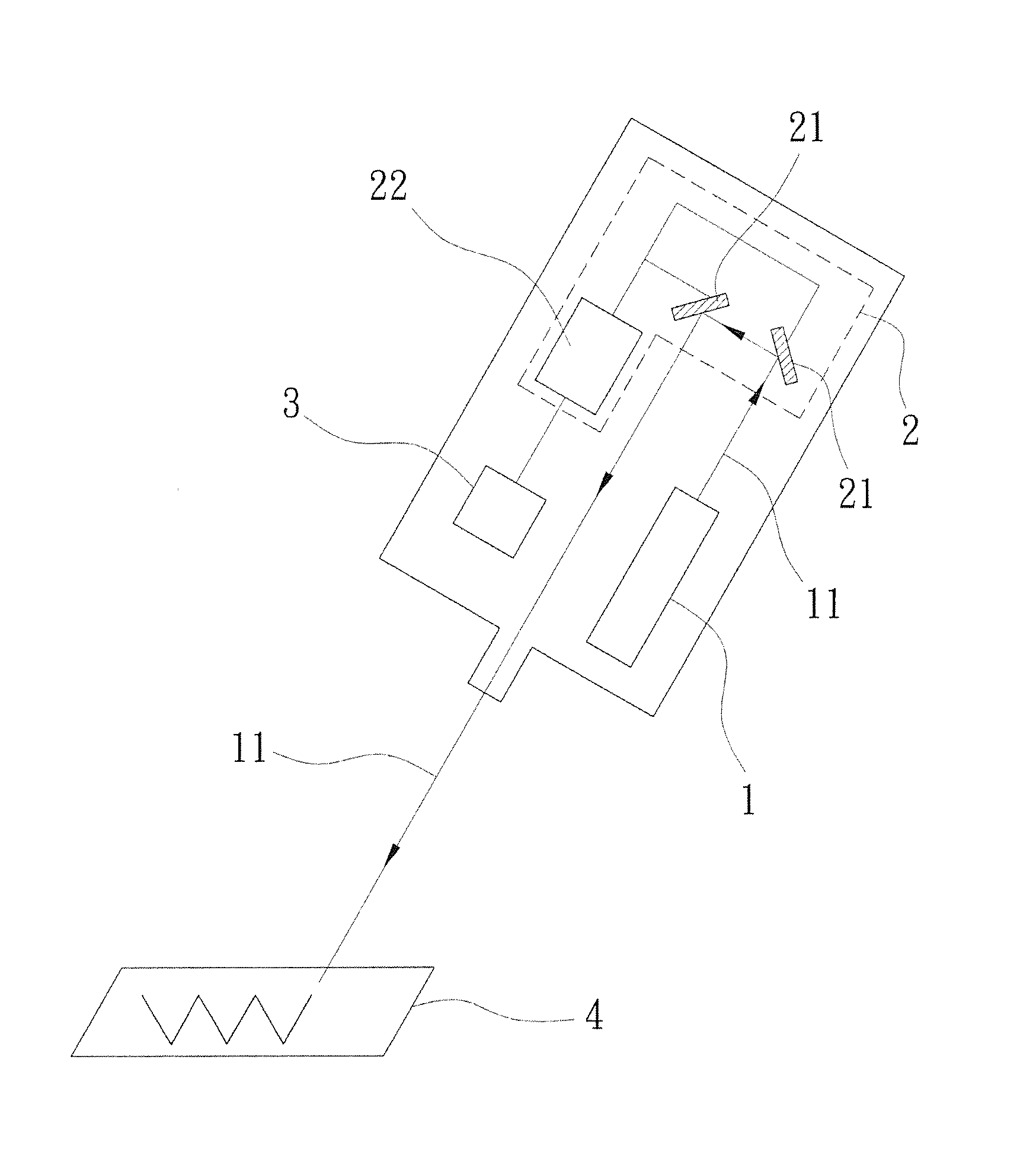
[0013]First, for a better understanding of the present invention, the basic concepts including laser collimation and UV-C sterilizing will be briefly described as followings. The term “laser” originated as an acronym for Light Amplification by Stimulated Emission of Radiation. Laser provides energy for active working media (gain medium) by the excitation system to amplify any photons passing through it. These photons can bounce within the laser cavity dozens to hundreds of times and finally go straight through the laser cavity to form a laser beam. Although the laser beam may disappear in the laser cavity if the forward direction of the laser beam is slightly non-parallel, the disappeared laser beam can be obtained again by fine tuning the system.

[0014]Therefore, laser beam has a better directivity, a better collimation, and the precise dosage controlling ability of the single-point fast scanning.

[0015]Furthermore, UV-C light has a wavelength of 253.7 nm, which is also generally kno...


PUM


Abstract

The invention relates to an ultraviolet laser sterilization system, comprising an ultraviolet laser module and a scanning module. The ultraviolet laser module emits an ultraviolet laser light with a wavelength ranging from 200 nm to 280 nm. The scanning module includes a plurality of reflectors for receiving the ultraviolet laser light, and a controller for controlling rotation of the reflectors to adjust an angle of emergence of the ultraviolet laser light for sterilizing a target.

Description

BACKGROUND OF THE INVENTION[0001]1. Field of the Invention[0002]The present invention relates to an ultraviolet laser sterilization system, especially to an ultraviolet laser light scanner for generating and receiving ultraviolet laser light having a wavelength of 266 nm. The system takes advantage of laser collimation as well as ultraviolet-C (UV-C) sterilization for effectively achieving the efficacy of comprehensive sterilization and disinfection rapidly and flawlessly.[0003]2. Description of Related Art[0004]There are ubiquitous microorganisms in the living environment, e.g. air, utensils and hands. Therefore, when conducting microbiological experiments in a laboratory or hospital, researchers should make all demanded utensils used in experiments to stay in a sterile state so as not to affect the experiments and the results thereof. A sterilization technology is a process on the premise of keeping the nature of matter to destroy all microorganisms, e.g. all bacteria, spores, vir...

Claims


Application Information

Patent Timeline
IPC IPC(8): A61L2/10G21K5/02
CPCA61L2/10G21K5/02A61L2209/12A61L2202/14A61L2202/24A61L2202/11A61L9/20A61L2209/111A61L2209/212
Inventor CHUI, HSIANG-CHENJUANG, SEAN SUNG-YENLIN, HSING-YINGHUANG, CHEN-HANLIAO, HUA-HSIEN
Owner NAT CHENG KUNG UNIV
Why Eureka
Try Eureka