Mechanical driver

a mechanical driver and driver technology, applied in the field of mechanical drivers, can solve the problems limiting the design opportunities, and limiting the complexity of the design, etc., and achieve the effect of reducing the volume of the pumping chamber

Active Publication Date: 2015-02-19
VICENTRA
View PDF6 Cites 15 Cited by
  • Summary
  • Abstract
  • Description
  • Claims
  • Application Information

AI Technical Summary

Benefits of technology

[0025]In a further embodiment of any of the above mechanical drivers according to the invention, the mechanical driver is used to drive the reciprocating piston of a micro-pump for infusing liquid drugs. The pump can comprise a pumping chamber having an inlet and outlet, wherein the volume of the pumping chamber is caused to change by the action of the mechanical driver. Such a pump can be part of a drug delivery device comprising a reservoir of drug maintained at a positive pressure such that when the pumping chamber is filling with liquid drug, the positive pressure of the drug reservoir assists in the filling of the pumping chamber. To prevent unintentional delivery of liquid drug from the drug reservoir, valves are provided at the inlet and outlet to the pumping chamber. The valves can be designed such that the inlet valve allows fluid to enter the pumping chamber from the drug reservoir when the pumping chamber is filling, and the outlet valve only allows fluid to pass through it when the volume of the pumping chamber is reduced by the action of the miniaturised mechanical driver.

Problems solved by technology

A number of limitations exist with these mechanical driving principles when incorporated into micro-pump designs.
A number of these mechanical drivers a too complex and lead to difficulties when designing a product where large numbers need to be manufactured, that are manufactured at high throughput and where the manufacturing process is required to deliver product at a cost effective price.
The complexity also limits the design opportunities when they are incorporated into micro-pumps.
Other limitations are that the components required in some of the mechanical drivers described above result in a product that is too costly or difficult to manufacture.
Yet another limitation is that the materials required when incorporating at least some of the mechanical drivers mentioned above into micro-pump products reduce the opportunities for using the product.
As an example, some materials are not compatible with the fluid media that the product is required to pump, because it degrades the commercially important components in the media.
Yet in other instances, some of the mechanical driving principles are not able to provide the accuracy required for micro-pumps required for drug delivery and other commercially important components.
And yet another limitation is that some of the above mechanical driving principles are not able to provide the repeatability required by certain drug delivery products.
And yet another limitation is that some of the above mechanical driving principles do not provide the power required by the drug delivery device when the mechanical driver is miniaturised.
However, SMA mechanical drivers have disadvantages that limit their use in applications that require high accuracy.
One disadvantage of using SMA in these devices is that it has a prominent strain hysteresis and its phase transition is dependent on temperature, stress, the direction of motion, and many other factors (J. D. Harrison, “Measurable Change Concomitant with SME Transformation,”Engineering Aspects of SMAs, eds.
Despite these often complex approaches to shape memory alloy control, the control of SMA is still difficult.
A limitation of these inventions is that these mechanical stops impart strain on the SMA and limit the performance of the driver and could also lead to failure.
By introducing the second piston, this invention increases the complexity of the device, making it more difficult to manufacture and less cost effective.
These added complications also increase the cost and complexity of manufacturing the device.
In both U.S. Pat. No. 6,656,158 and U.S. Pat. No. 6,375,638, the complexity of the device described increases the complexity of the manufacturing process and the cost-effectiveness of the manufactured device.

Method used


Image

  • Mechanical driver
  • Mechanical driver
  • Mechanical driver

Examples


first embodiment

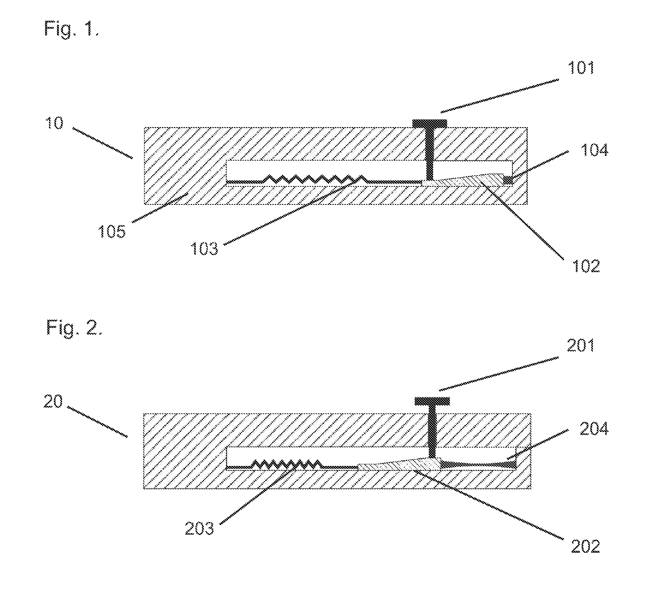
[0052]the mechanical driver is shown in FIG. 1. The mechanical driver is a miniature mechanical driver. FIG. 1 shows the miniaturised mechanical driver 10 in its non activated state. The miniaturised mechanical driver 10 comprises a wedge shaped member 102. The wedge shaped member 102 is arranged so that it can move in one plane and in an essentially linear direction. The wedge shaped member 102 has at least one angled surface arranged so that it forms an angle with the direction of travel of the wedge shaped member 102. A shape memory actuator 103 is fixed to the wedge shaped member 102 at one end and to the frame 105 of the miniaturised mechanical driver 10. The shape memory actuator 103 is arranged so that it acts along the linear direction of travel of the wedge shaped member 102. The shape memory actuator 103 is also referred to as shape memory alloy. Both terms relate to an actuator made from a shape memory alloy material. A return spring 104 is attached at one end to the wedg...

second embodiment

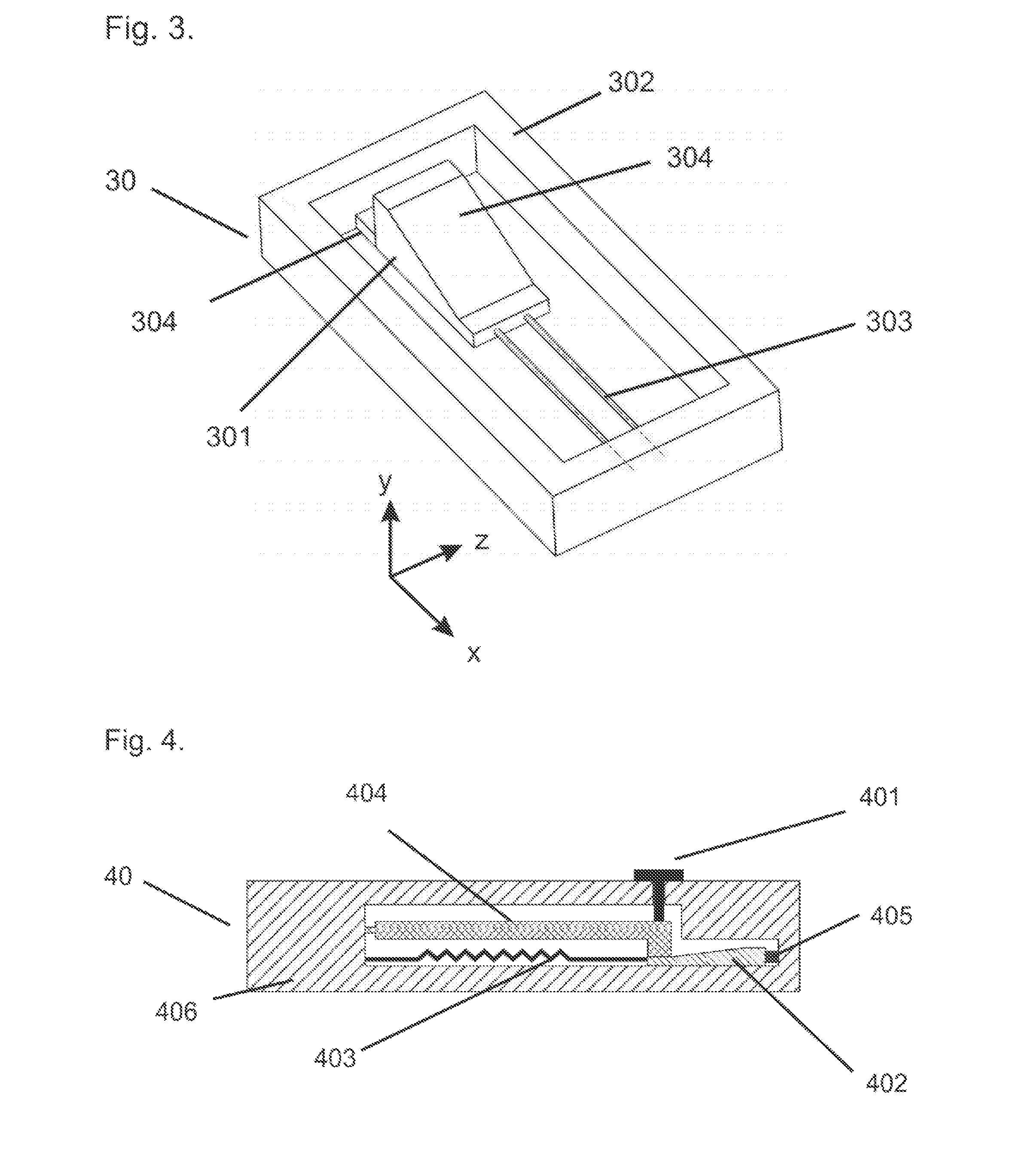
[0058]FIG. 5 shows the activated form of the mechanical driver according to the present invention. The shape memory alloy 503 is heated preferably by passing an electric current through it. The heated shape memory alloy 503 contracts and moves the wedge shaped member 502 from its first position shown in FIG. 4 to its second position shown in FIG. 5. When the wedge shaped member 502 moves from its first position to its second position it elongates the return spring 505. When the wedges shaped member 502 moves from its first position to its second position it also moves the lever 504 from its first position shown in FIG. 4 to its second position shown in FIG. 5. The lever moves in an angular direction about the pivot point 507. When the lever 504 moves to its second position it moves the piston 501 from its first position shown in FIG. 4 to its second position shown in FIG. 5. In the mechanical driver 50, the lever 504 is connected to the frame at the fixed rotation point 507. The pis...

fourth embodiment

[0063]When the wedge shaped member 902 moves from its first position to its second position it moves the lever 904 from its first position shown in FIG. 8 to its second position shown in FIG. 9. When the lever 904 moves to its second position it moves the piston 901 from its first position shown in FIG. 8 to its second position shown in FIG. 9. FIG. 9 furthermore shows the piston 901 and the piston drive point 906 of the lever 904 of the mechanical driver 90. the mechanical driver according to the present invention has the advantage of increasing the distance the wedge shaped member is able to displace the lever and the piston for a given length of contraction by the shaped memory alloy without an increase in the angle of the angled surface.

[0064]It will be appreciated by those skilled in the art that the wedge shaped member and the frame described in the fourth embodiment of the mechanical driver according to the present invention can be incorporated into the first and second embod...


PUM


Abstract

A mechanical driver comprising a wedge shaped member operatively coupled to a shape memory alloy such that the shape memory alloy is able to displace the wedge shaped member in an essentially linear direction. The wedge shaped member is in constant contact with a lever arranged so that it can rotate about a fixed pivot point. A piston is arranged such that it is constant contact with the lever at a point between the pivot point of the lever and the contact point between the lever and the wedge shaped member. Return springs are provided to return the piston, lever and wedge shaped member to their respective start positions. Activation of the shape memory alloy displaces the wedge shaped member along its linear direction and this causes the lever to be deflected about its pivot point and the piston to be deflected in an essentially linear direction that is perpendicular to the linear direction of travel of the wedge shaped member.

Description

BACKGROUND[0001]This invention relates to a mechanical driver. Said mechanical driver can be miniature mechanical driver and is often used in a micro-pump. The micro-pump can be used as the fluid pumping device of a drug delivery system.[0002]A variety of mechanical drivers have been described for providing the mechanical displacement required in devices designed for pumping fluids. Examples of these mechanical drivers include devices operating on thermo-pneumatic (U.S. Pat. No. 4,265,600 and U.S. Pat. No. 6,520,753), electrostatic (U.S. Pat. No. 6,168,395 and U.S. Pat. No. 5,362,213), piezo electric (U.S. Pat. No. 4,596,575 and U.S. Pat. No. 6,827,559), thermo-hydraulic (GB2443261), bimetallic (U.S. Pat. No. 5,611,676), stepper motors (EP2072072) and magnetic (U.S. Pat. No. 3,819,305 and U.S. Pat. No. 7,922,462) mechanical driving principles.[0003]A number of limitations exist with these mechanical driving principles when incorporated into micro-pump designs. A number of these mech...

Claims


Application Information

Patent Timeline
Patent Type & Authority Applications(United States)
IPC IPC(8): A61M5/145
CPCA61M5/1454A61M2005/14506A61M2207/00A61M2205/0266A61M5/1452A61M2205/0244F03G7/065F04B9/02F04B17/00F04B19/006F04B43/043A61M5/14216F04B17/03A61M5/145F04B19/00
Inventor CEFAI, JOSEPH JOHN
Owner VICENTRA
Why Eureka
Try Eureka