
Variable displacement engine control system and method

a control system and variable displacement technology, applied in the direction of electric control, ignition automatic control, instruments, etc., can solve the problems of exacerbated combustion problems, less stable combustion during reactivation, and degraded combustion stability during the transition, so as to reduce engine load or torque, improve the stability of restarting combustion, and reduce torque disturbances during a transition out of vde mode of operation

Active Publication Date: 2015-02-19
FORD GLOBAL TECH LLC
View PDF26 Cites 32 Cited by
  • Summary
  • Abstract
  • Description
  • Claims
  • Application Information

AI Technical Summary

Benefits of technology

The patent describes a method for improving engine performance by selectively deactivating engine cylinders and then reactivating them with split fuel injection. This helps to improve restart combustion stability and reduces torque disturbances during a transition out of a VDE mode of operation. The use of EGR during VDE operation provides additional fuel economy benefits, but it also causes combustion stability issues and may need to be regenerated during reactivation. The split injection and spark retard help to address these issues and improve engine performance.

Problems solved by technology

However the inventors herein have identified potential issues with such an approach.
As one example, combustion stability may be degraded during the transition.
The lighter cylinder loads generally have less stable combustion and the interaction with the transient fuel compensation, and other cylinder conditions that are different than the operating cylinders due to cooling during deactivation, may contribute to less stable combustion during reactivation.
If the engine is equipped for exhaust gas recirculation, EGR control used during the transition may exacerbate the combustion issues.
In particular, the EGR may continue to interfere with the lighter cylinder load until the EGR delivered to the cylinders has been sufficiently bled down to reduce combustion issues.
However, due to the slow response time of the CMCV (e.g., the CMCV not shutting quickly enough when transitioning to the lower cylinder load), combustion stability may be compromised.
The poor combustion conditions can also lead to slow burns or even misfires.
Overall, combustion stability and engine performance may be degraded.
Even though the EGR valve is closed, due to transport delays along the EGR passage, EGR may purge from the air intake system slower than desired, resulting in increased EGR dilution of intake air during the reactivation.

Method used


Image

  • Variable displacement engine control system and method
  • Variable displacement engine control system and method
  • Variable displacement engine control system and method

Examples


Embodiment Construction

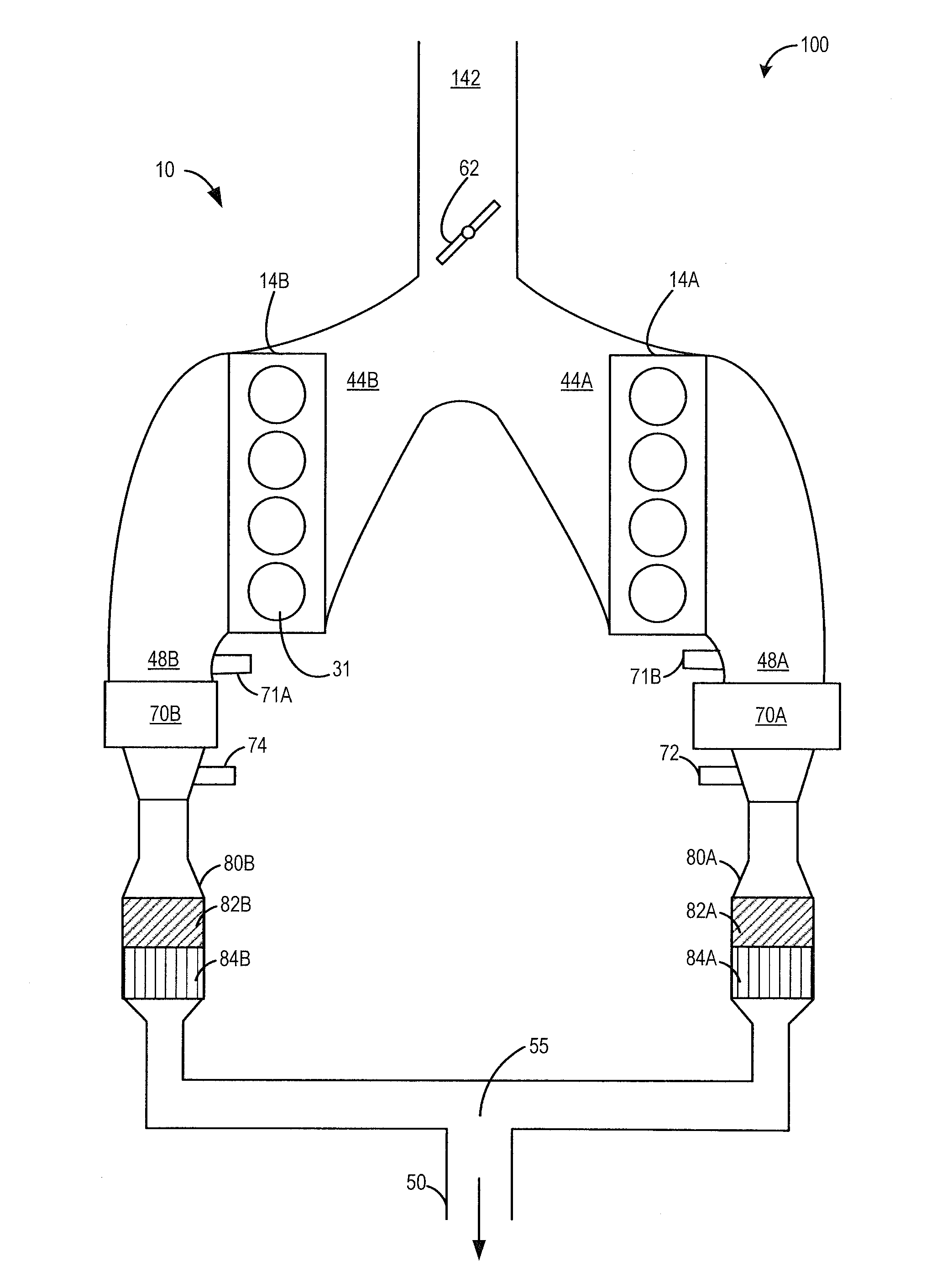
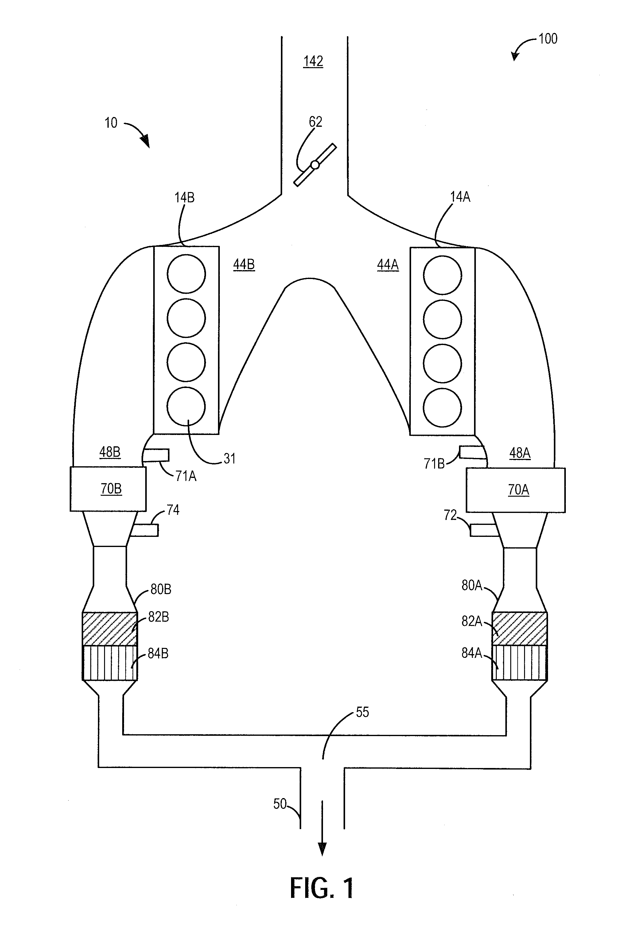
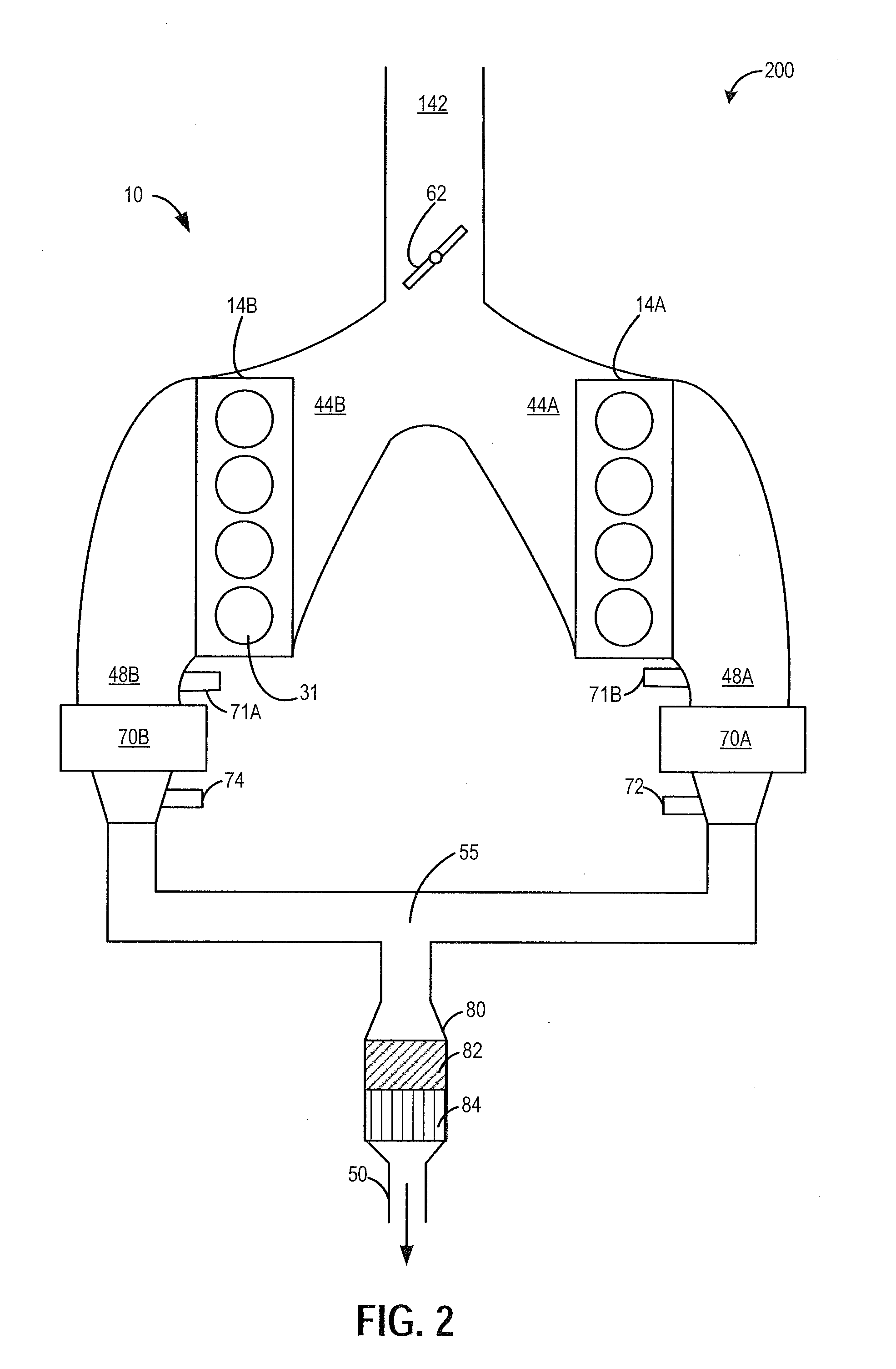
[0016]Methods and systems are provided for adjusting a fuel injection profile when operating a variable displacement engine, such as the engine of FIGS. 1-3. The fuel injection profile may be adjusted for active cylinders during a VDE mode of operation to expedite exhaust catalyst heating and thereby prolong operation in the VDE mode. Alternatively, the fuel injection profile may be adjusted for reactivated cylinders during a transition from VDE mode to non-VDE mode of operation to reduce torque disturbances and combustion stability issues while improving exhaust emissions. A controller may be configured to perform a routine, such as the routine of FIG. 4, to shift a fuel injection profile for selected cylinder from a single intake stroke injection to at least a first intake stroke injection and a second compression stroke injection. For example, as shown at FIG. 5 and FIG. 7, the controller may shift the active cylinders during a VDE mode to split fuel injection. As another example...


PUM


Abstract

Methods and systems are provided for improving the performance of a variable displacement engine. Split injection and spark retard may be used in active cylinder during a VDE mode to heat an exhaust catalyst and extend the duration of VDE mode operation. Split injection and spark retard may also be used in reactivated cylinders at a time of cylinder reactivation to improve restart combustion stability.

Description

FIELD[0001]The present application relates to adjusting fuel injection strategy when operating in or transitioning between modes in a variable displacement internal combustion engine (VDE).BACKGROUND AND SUMMARY[0002]Engines may be configured to operate with a variable number of active or deactivated cylinders to increase fuel economy, while optionally maintaining the overall exhaust mixture air-fuel ratio about stoichiometry. Such engines are known as variable displacement engines (VDE). In some examples, a portion of an engine's cylinders may be disabled during selected conditions, where the selected conditions can be defined by parameters such as a speed / load window, as well as various other operating conditions including vehicle speed. A VDE control system may disable selected cylinders through the control of a plurality of cylinder valve deactivators that affect the operation of the cylinder's intake and exhaust valves, or through the control of a plurality of selectively deact...

Claims


Application Information

Patent Timeline
IPC IPC(8): F02D17/02F02D43/00
CPCF02D43/00F02D17/02F02D41/0087F02D41/0245F02D41/064F02D41/3836F02D41/402F02P5/1512F02D41/0025F02D41/005F02D2200/021F02D2200/0802Y02T10/12Y02T10/40F02M26/00F01N3/10F02D41/00F02P5/15
Inventor GLUGLA, CHRIS PAULSCHWOCHERT, STEVENJAHR, KEN
Owner FORD GLOBAL TECH LLC
Learn More