
Electrode material for thermal-fuse movable electrode

Active Publication Date: 2015-02-26
TANAKA PRECIOUS METAL IND
View PDF2 Cites 1 Cited by
  • Summary
  • Abstract
  • Description
  • Claims
  • Application Information

AI Technical Summary

Benefits of technology

The electrode material described in this patent is suitable for the movable electrode of a thermal fuse. By combining copper and silver in a special alloy, the material is made more cost-effective. Additionally, an intermediate layer is included to ensure stable contact with the fuse case and maintaining strength and spring properties under heating. The material has good welding resistance, making it ideal for the movable electrode.

Problems solved by technology

This is because, the movable electrode is energized in contact with the lead wire constantly, and when welding is generated, it becomes a factor of the operational failure of the thermal fuse.

Method used


Image

  • Electrode material for thermal-fuse movable electrode
  • Electrode material for thermal-fuse movable electrode

Examples


example 1

[0029]First, each metal was weighed so as to have an alloy composition of 90.0% by mass of Ag, 10.0% by mass of Cu, and an Ag—Cu alloy was melted and cast. Thereafter, an Ag—Cu alloy ingot was rolled to a thickness of 4.15 mm and cut to manufacture an Ag—Cu alloy plate with a width of 115 mm and a length of 195 mm. Moreover, an oxygen-free copper ingot was rolled to manufacture a Cu plate with a width of 120 mm, a length of 200 mm and a thickness of 9 mm, and the above Ag—Cu alloy plate was stacked on both sides of this Cu plate. After cold crimping at a pressure of 150 t, the laminate was maintained at 800° C. for 60 minutes in a mixed gas of nitrogen and hydrogen, and then hot crimped at a pressure of 100 ton. The crimped three-layer (Ag—Cu alloy / Cu / Ag—Cu alloy) clad material was subjected to rolling processing to manufacture a clad material tape.

[0030]Next, the clad material tape described above was rolled to 450 μm, to be a three-layer clad material tape made of an Ag—Cu alloy l...

example 2

[0031]In Example 1, in the internal oxidation of the three-layer clad material (Ag—Cu alloy / Cu / Ag—Cu alloy), the heat treatment time was set at 10 hours, thereby forming an Ag—CuO alloy layer with a thickness of 91 μm and an Ag—Cu alloy layer with a thickness of 19 μm. Thereafter, the resulting alloy plate was rolled in the same manner as in Example 1 to manufacture a clad material tape with a five-layer structure. The manufactured clad material tape has a total thickness of 89 μm of Ag—CuO (18.3 μm) / Ag—Cu (3.7 μm) / Cu (45 μm) / Ag—Cu (3.7 μm) / Ag—CuO (18.3 μm). The resulting clad material tape was cut to make an electrode material for evaluation.

example 3

[0032]In Example 1, in the internal oxidation of the three-layer clad material (Ag—Cu alloy / Cu / Ag—Cu alloy), the heat treatment time was set at 3 hours, thereby forming an Ag—CuO alloy layer with a thickness of 55 μm and an Ag—Cu alloy layer with a thickness of 55 μm. Thereafter, the resulting alloy plate was rolled in the same manner as in Example 1 to manufacture a clad material tape with a five-layer structure. The manufactured clad material tape has a total thickness of 89 μm of Ag—CuO (11 μm) / Ag—Cu (11 μm) / Cu (45 μm) / Ag—Cu (11 μm) / Ag—CuO (11 μm). The resulting clad material tape was cut to make an electrode material for evaluation.


PUM

PropertyMeasurementUnit
Temperatureaaaaaaaaaa
Timeaaaaaaaaaa
Percent by massaaaaaaaaaa

Abstract

The present invention is an electrode material constituting a movable electrode of a thermal fuse, having a five-layer clad structure including a core material layer, an intermediate layer formed on the both sides of the core material layer, and a surface layer formed on the intermediate layer, wherein the core material layer includes Cu, the intermediate layer includes an Ag—Cu-based alloy, the surface layer includes an Ag—CuO-based oxide-dispersed strengthened alloy, and the ratio of the thickness of the intermediate layer to the thickness of the surface layer (intermediate layer / surface layer) is 0.2 or more and 1.0 or less. This electrode material can be manufactured by partially internally oxidizing a three-layer clad material in which plate materials made of an Ag—Cu-based alloy are clad-jointed to both sides of the plate material made of Cu.

Description

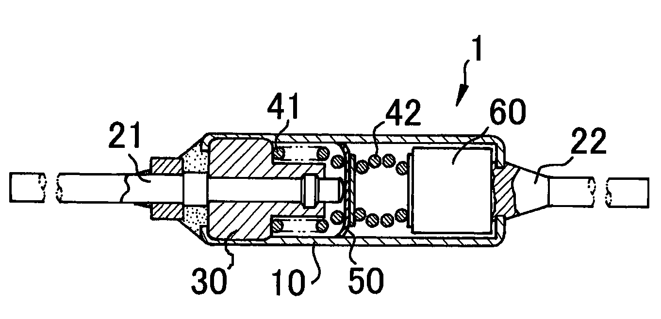
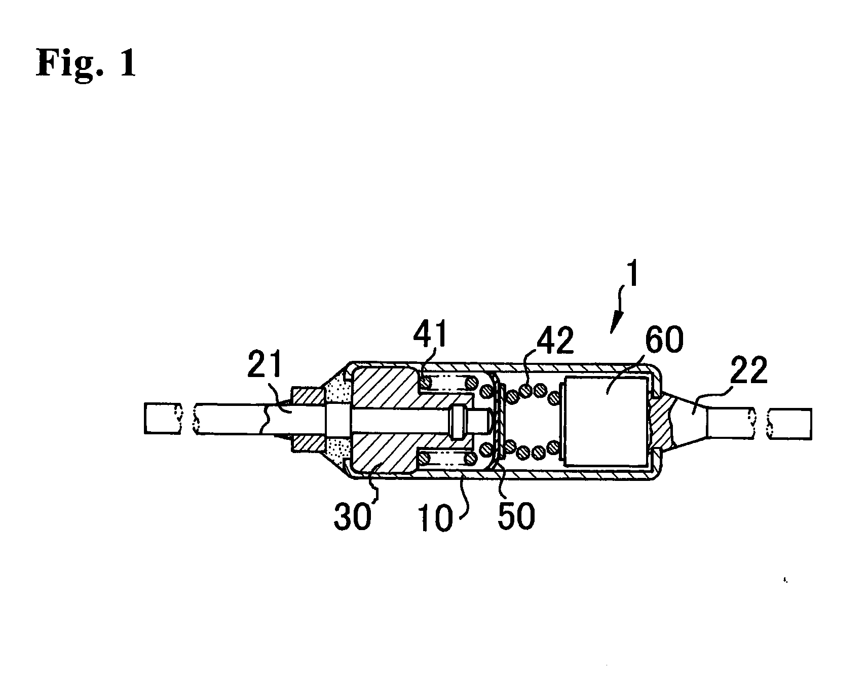
TECHNICAL FIELD[0001]The present invention relates to an electrode material, especially, a material suitable for a thermal-fuse movable electrode.BACKGROUND ART[0002]FIG. 1 illustrates a constitution of a general thermal fuse. In thermal fuse 1, lead wires 21 and 22 are connected to case 10 made of a conductive metal, and insulating material 30, springs 41 and 42, movable electrode 50 and fuse element 60 are installed inside the case 10. The spring 41 is disposed between the movable electrode 50 and the insulating material 30, and the spring 42 is disposed between the movable electrode 50 and the fuse element 60. The movable electrode 50 is movable while contacting with the inner surface of the case 10. At normal time (the state of FIG. 1), the thermal fuse is energized from the lead wire 21 to the movable electrode 50 and the case 10, further to the lead wire 22. Then, when the thermal fuse is overheated due to an excess load on the connected electronic device or the like, the fuse...

Claims


Application Information

Patent Timeline
IPC IPC(8): H01H85/143
CPCH01H85/143B32B15/01C22C1/02C22C5/06C22C5/08H01H1/0237H01H37/765C22F1/14B32B15/018C22C9/00H01H11/042H01H2011/047
Inventor SAKAGUCHI, OSAMUTAKAHASHI, MICHIYAADACHI, SHINYA
Owner TANAKA PRECIOUS METAL IND
Learn More