Multicore fiber waveguide coupler

Active Publication Date: 2015-03-05
IBM CORP
View PDF9 Cites 34 Cited by
  • Summary
  • Abstract
  • Description
  • Claims
  • Application Information

AI Technical Summary

Benefits of technology

The invention provides a cheap and easy-to-use optical connector that can link multicore fibers or optelectronic elements to multicore fibers.

Problems solved by technology

Multicore fibers have been cited in the literature as early as 1979 and various newer types of multimode and single-mode multicore fibers have been proposed over the years, but they have to date not been a major commercial success.
This is largely due to the absence of a simple and low-cost optical connector to couple between multicore fibers or between optoelectronic elements and multicore fibers.
Rotational alignment is critical and has not been successfully addressed in a passive alignment process.
Active alignment of each individual fiber would be costly.
Using two-lens optical relays, efficient coupling could be possible, but density between neighboring fibers (typically 125-250-μm diameter) is limited, thereby giving up some of the advantage of multicore fibers.
However, none of these concepts demonstrates coupling between multicore fibers and optical waveguides.
However, coupling multicore fibers to optical waveguides is not disclosed.
Unlike passive alignment, active alignment of multicore fibers is a time-consuming and costly process that is unsuitable for high-volume applications demanding ultra-low cost connections.
However, this is also an active fiber alignment device and no means for passive rotational fiber alignment is described.
Also, coupling to optical waveguide elements is not disclosed, and the fiber type described in this work is a photonic crystal fiber, which is a very specific sub-type of multicore fibers with limited applications.
However, in-plane coupling is limited to a substrate with a single plane.

Method used


Image

  • Multicore fiber waveguide coupler
  • Multicore fiber waveguide coupler
  • Multicore fiber waveguide coupler

Examples


Embodiment Construction

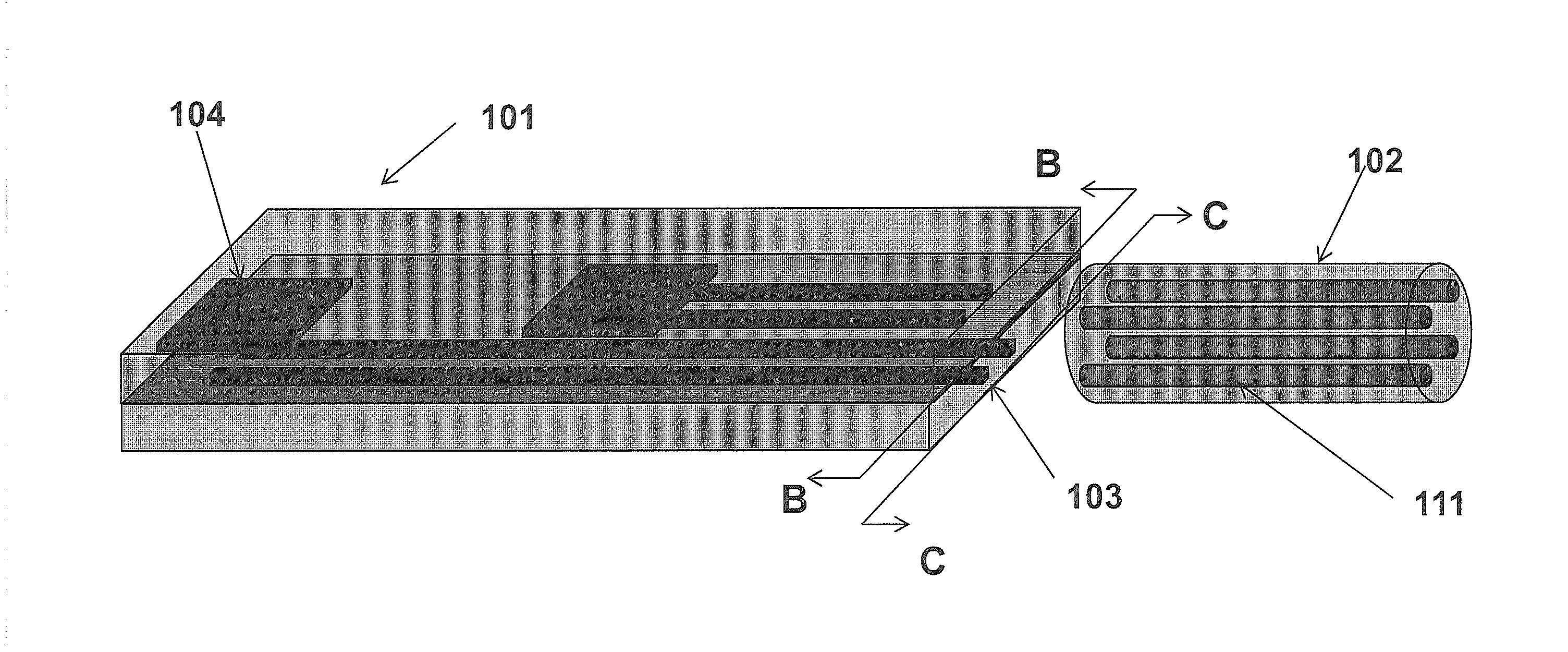
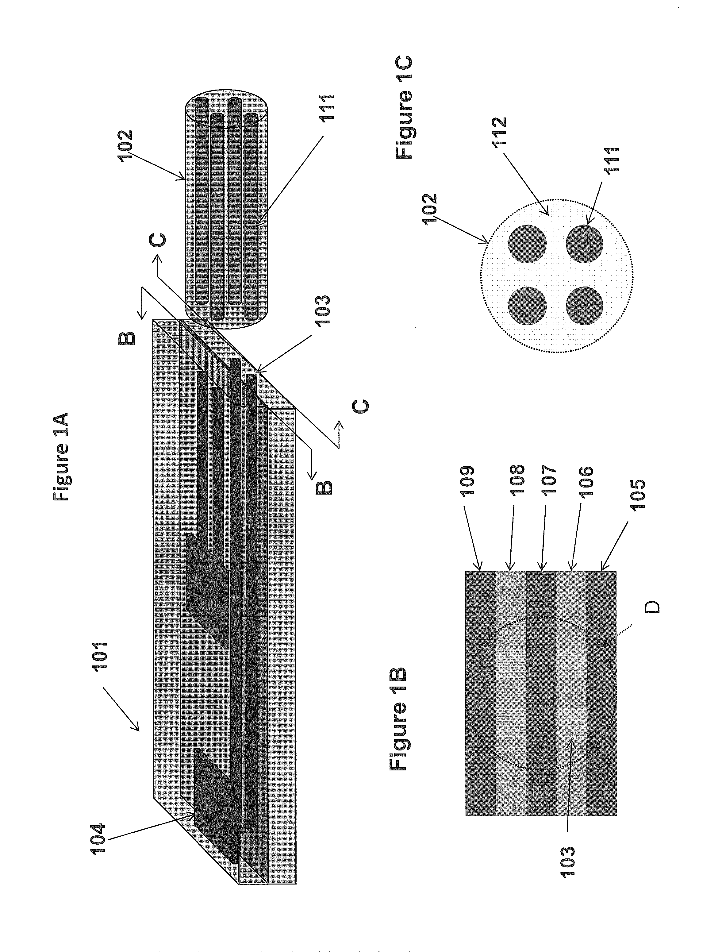
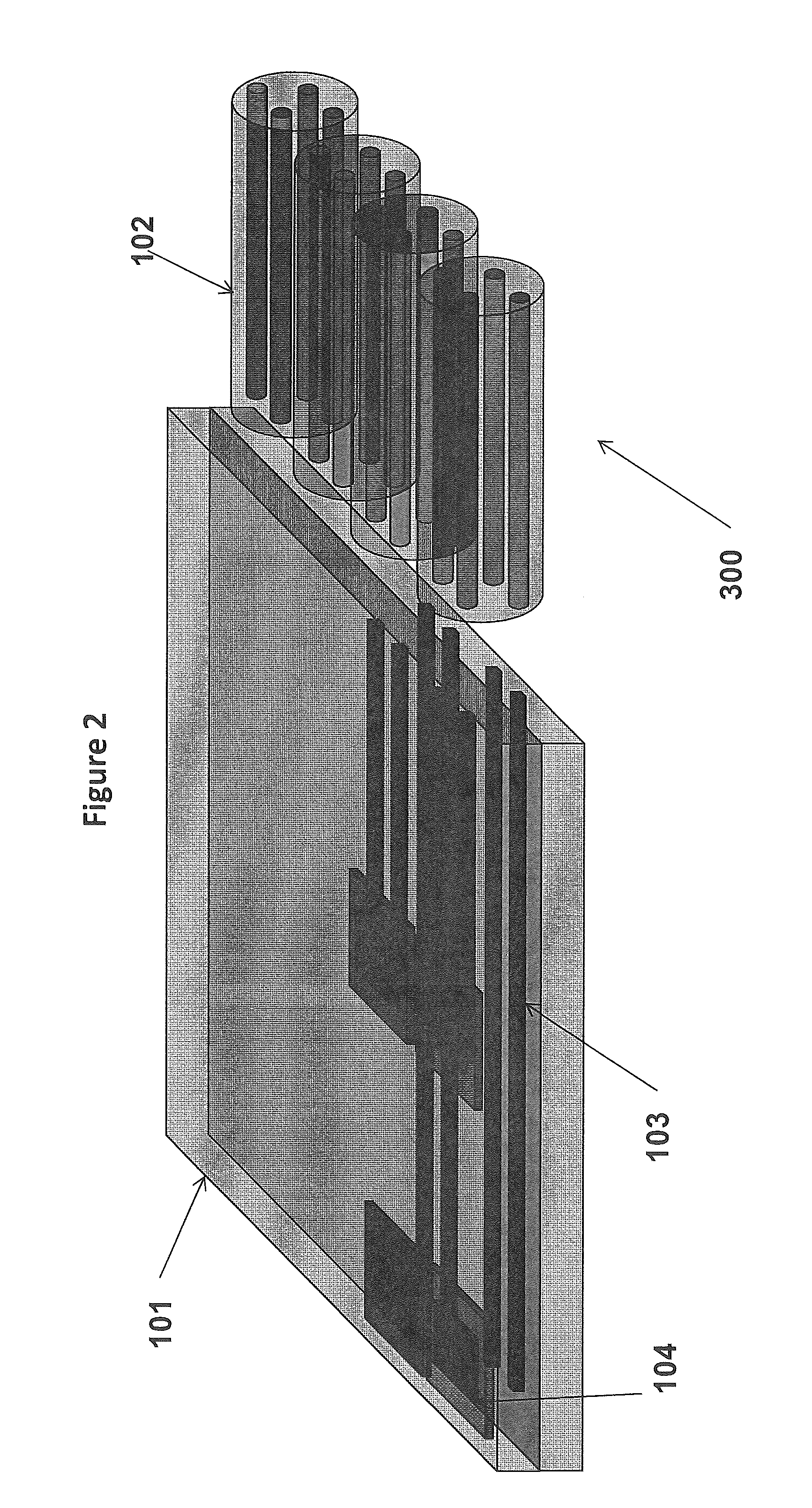
[0041]In an exemplary embodiment, coupling an optical waveguide element to a multicore fiber can be applied as follows. A waveguide element can be used as intermediate coupling element to connect optoelectronic devices to multicore fibers. Exemplary optical waveguides may be integrated in various substrates, such as polymer waveguides on a printed circuit board or flex substrate.

[0042]Exemplary embodiments of the invention also apply to optical waveguides integrated on a glass or semiconductor carrier, and a chip or chip stack, such as in silicon nanophototonic technology.

[0043]Some exemplary embodiments of this invention incorporate waveguide elements with multiple layers of optical waveguides. Some exemplary embodiments of this invention include pitch conversion in the waveguide element, in order to decouple the layout of the optoelectronic devices from the layout of the multicore fiber. As a result, standard optoelectronic devices or device arrays can be used.

[0044]Some exemplary...


PUM

PropertyMeasurementUnit
Thicknessaaaaaaaaaa
Shapeaaaaaaaaaa
Transparencyaaaaaaaaaa

Abstract

An optical connector includes a fiber element incorporating one or more optical fibers, the optical fiber including a plurality of cores, and an optical element including an array of optical waveguides arranged in one or more layers so as to match the geometry of the plurality of cores of the optical fiber.

Description

STATEMENT REGARDING FEDERALLY SPONSORED RESEARCH AND DEVELOPMENT[0001]The invention disclosed herein was made with U.S. Government support under Contract No. H98230-07-C-0409 awarded by the National Security Agency. The Government has certain rights in this invention.BACKGROUND OF THE INVENTION[0002]1. Field of the Invention[0003]The present invention relates generally to fiber optic interconnections. This invention relates in particular to coupling light between multicore fibers and elements with optical waveguides.[0004]2. Description of the Related Art[0005]Multicore fibers have a multitude of cores embedded in a common cladding. As such, they can transport more bandwidth per fiber than standard fibers with a single core and hence lead to a potential cost reduction. Multicore fibers have been cited in the literature as early as 1979 and various newer types of multimode and single-mode multicore fibers have been proposed over the years, but they have to date not been a major comme...

Claims


Application Information

Patent Timeline
IPC IPC(8): G02B6/02G02B6/42
CPCG02B6/425G02B6/02042G02B6/30G02B6/3652G02B6/3897G02B6/4214G02B6/423Y10T29/49826
Inventor DOANY, FUADKUCHTA, DANIEL M.PEPELJUGOSKI, PETAR K.SCHARES, LAURENT
Owner IBM CORP
Why Eureka
Try Eureka