
Carbon nanotubes having a bimodal size distribution

Inactive Publication Date: 2015-03-05
SEERSTONE
View PDF6 Cites 26 Cited by
  • Summary
  • Abstract
  • Description
  • Claims
  • Application Information

AI Technical Summary

Benefits of technology

The present patent is about a new mixture of carbon nanotubes that have a bi-modal distribution of sizes. This mixture includes a primary population of larger diameter carbon nanotubes and a distinct secondary population of smaller diameter carbon nanotubes. The carbon nanotubes can have various shapes and sizes, and the secondary population is distributed throughout the primary population. The bi-modal composition has unique engineering properties that combine the strength of larger multi-wall carbon nanotubes with the conductance properties of smaller single-wall carbon nanotubes. This new mixture of carbon nanotubes can be useful in various applications.

Problems solved by technology

One obstacle to widespread use of CNTs has been the cost of manufacture.
In current practice, capture and sequestration of the carbon dioxide entails significant cost.

Method used


Image

  • Carbon nanotubes having a bimodal size distribution
  • Carbon nanotubes having a bimodal size distribution
  • Carbon nanotubes having a bimodal size distribution

Examples


example 1

Sample 85

[0167]

CarbonReducingExampleOxideAgentCatalystConditionsExample 1CO2H2mild steel pipeP = 113 kPaForestTemp = 700° C.Growth bi-Time = 4 hourmodal CNTs

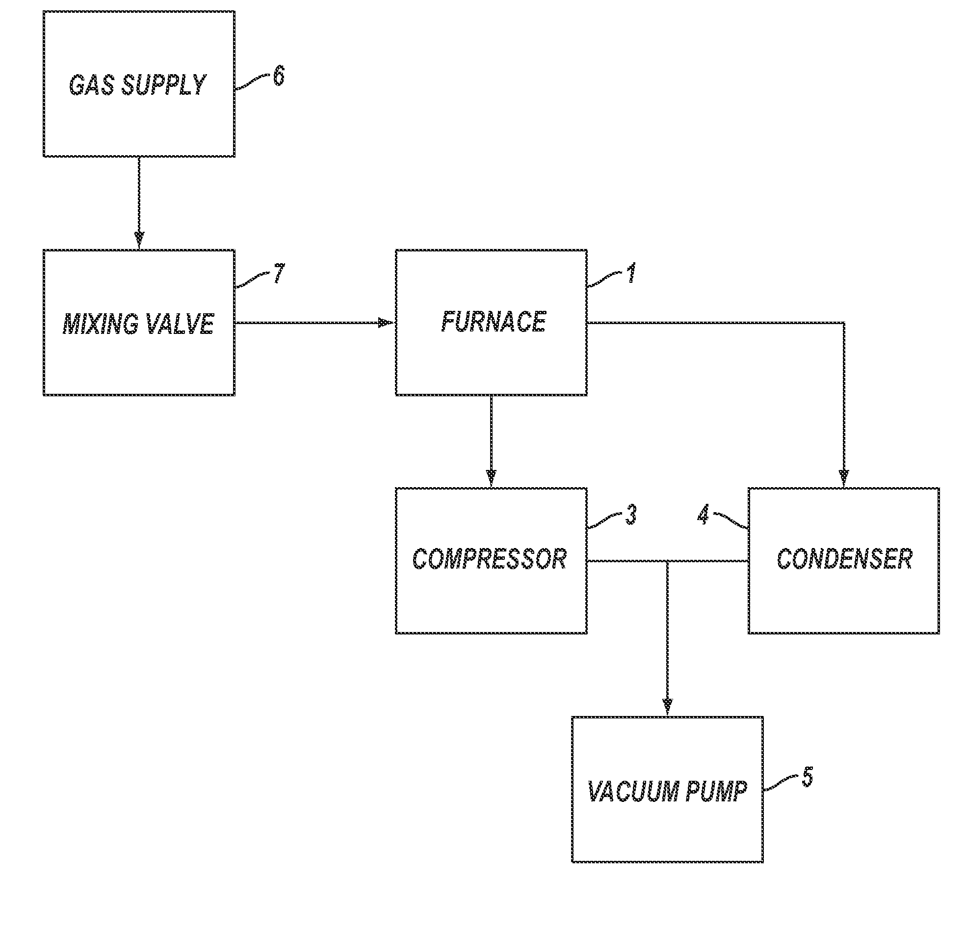
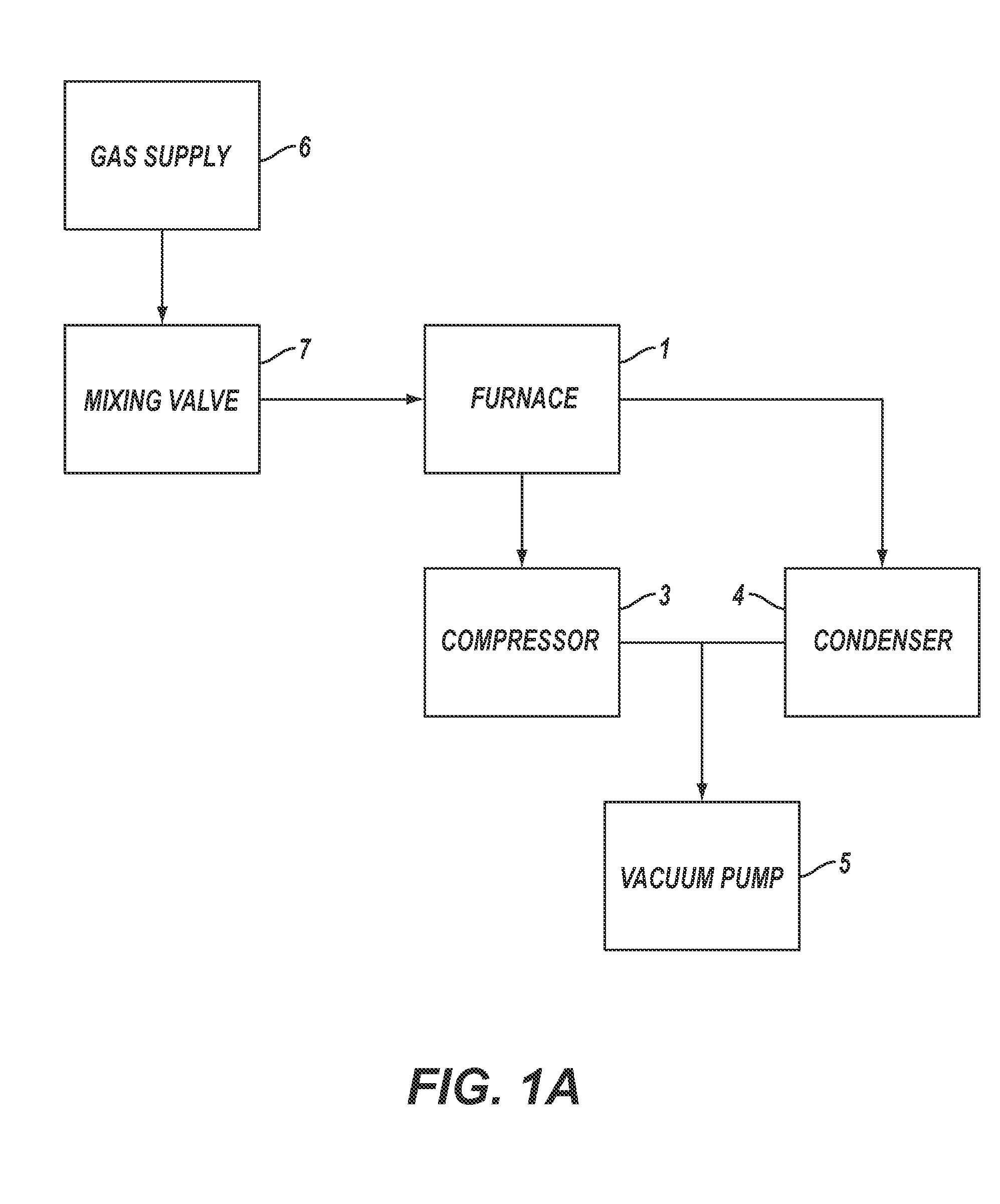
[0168]For Example 1, the reactor pipe was a mild steel pipe (schedule 40) 5 cm (2 inches) in diameter and 1.2 m (4 feet) long inserted into the tube furnace 1. The vacuum pump 5 was started and hydrogen was used to purge the experimental apparatus for 30 seconds. After 30 seconds, the vacuum pump was turned off, the compressor 3 was turned on, the refrigerated condenser 4 was turned on and the hydrogen gas continued to flow until the pressure was about 113 kPa (850 torr), at which point the hydrogen gas flow was shut off. The tube furnace 1 was then turned on.

[0169]When the tube furnace 1 temperature reached the set point temperature of 700° C., the vacuum pump 5 was turned on, and reaction gases in a stoichiometric mixture of carbon dioxide and hydrogen, from gas supply 6 controlled by mixing valve 7, were used to purge the exp...

example 2

Sample 112

[0173]

CarbonReducingExampleOxideAgentCatalystConditionsExample 2CO2H2304 stainless steel P = 101 kPaMulti Walland quartz diskTemp =Carbon~600° C.NanotubesTime = 1 hour

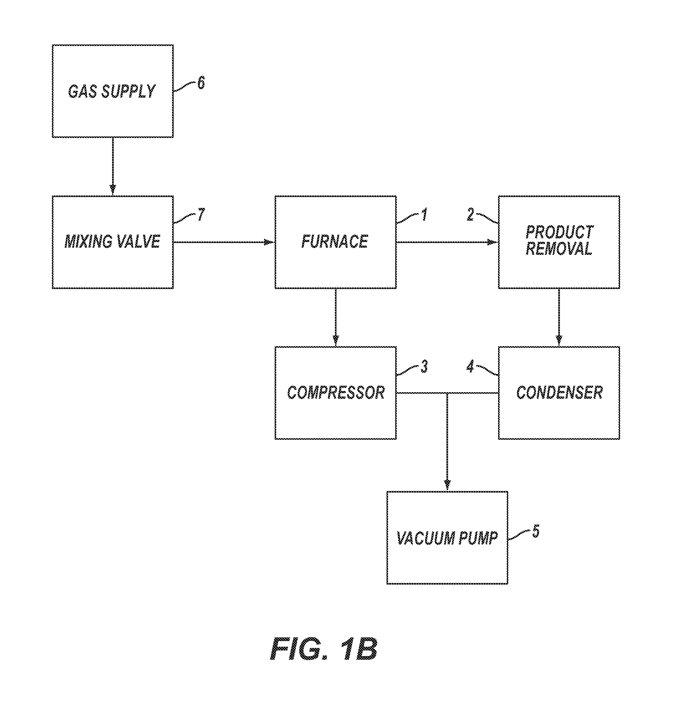
[0174]For Example 2, a sample quartz disk was placed flat on a 304 stainless steel wafer, which was used as the catalyst. The 304 stainless steel catalyst wafer was placed in the tube furnace 1 at approximately the center line. The vacuum pump 5 was started and helium was used to purge the experimental apparatus for five minutes. After five minutes the vacuum pump was turned off, the compressor 3 was turned on, the refrigerated condenser 4 was turned on and the helium gas continued to flow until the pressure was 91.0 kPa (680 Torr), at which point the gas flow was shut off. The furnace was then turned on.

[0175]When the furnace 1 temperature reached the set point temperature of 680° C., the vacuum pump 5 was turned on and reaction gases in a stoichiometric mixture of carbon dioxide and hydrogen, from gas suppl...

example 3

Sample 35

[0179]

Carbon ReducingExampleOxideAgentCatalystConditionsExample 3CO2H2316 L stainlessP = 101 kPaMulti Wallsteel waferTemp =Carbon~650° C.NanotubesTime = 1 hour

[0180]For Example 3, a 316L stainless steel wafer was used as the catalyst. The 316L stainless steel wafer was placed in the furnace 1 at approximately the center line. The compressor 3 was turned on, the refrigerated condenser 4 was turned on, the vacuum pump 5 was turned on and a purge gas comprising helium from the gas supply 6 controlled by the mixing valve 7, was introduced into the experimental apparatus. After five minutes of purging, the vacuum pump was shut off and the helium purge gas continued to flow until the pressure of the experimental apparatus was 91 kPa, at which point the purge gas flow was shut off. The furnace was then turned on.

[0181]When the furnace 1 temperature reached about 640° C., the vacuum pump 5 was started and reaction gases in a stoichiometric mixture of carbon dioxide and hydrogen, fr...


PUM


Abstract

A composition comprising a mixture of carbon nanotubes having a bi-modal size distribution are produced by reducing carbon oxides with a reducing agent in the presence of a catalyst. The resulting mixture of nanotubes include a primary population of multiwall carbon nanotubes having characteristic diameters greater than 40 nanometers, and a secondary population of what are apparently single wall nanotubes with characteristic diameters of less than 30 nanometers. The resulting mixture may also contain one or more other allotropes and morphologies of carbon in various proportions. The mixture of carbon nanotubes has specific apparently uncommon properties, including unusual resistivity and density

Description

PRIORITY CLAIM[0001]This application claims the benefit of the filing date of U.S. Provisional Patent Application Ser. No. 61 / 637,229, filed Apr. 23, 2012, for “Carbon Nanotubes Having a Bimodal Size Distribution,” the disclosure of which is hereby incorporated herein in its entirety by this reference.TECHNICAL FIELD[0002]Embodiments of the disclosure relate generally to compositions consisting of carbon nanotubes having a wide range of size distributions and having a generally bi-modal size distribution. The disclosure further provides methods for the production of a bi-modal composition comprised substantially of two or more distinct populations of carbon nanotubes, the primary growth population comprised of characteristically significantly larger carbon nanotubes (typically multiwall carbon nanotubes), accompanied by a secondary growth population comprised of characteristically much smaller nanotubes (typically single-wall carbon nanotubes).BACKGROUND[0003]U.S. Patent Publication...

Claims


Application Information

Patent Timeline
IPC IPC(8): C01B31/02
CPCC01B2202/00C01B31/0233C01B32/16C01P2004/53
Inventor NOYES, DALLAS B.
Owner SEERSTONE
Learn More