Analog amplifiers and comparators

a technology of analog amplifiers and comparators, applied in differential amplifiers, amplifiers with semiconductor devices/discharge tubes, amplifiers, etc., can solve the problems of limiting the operating voltage to near a volt or less, severe limiting of analog signal swing, and inability to keep up with the integration of analog circuits/designs, etc., to achieve superior signal-to-noise ratio, reduce noise, and high performance

Active Publication Date: 2015-03-12
SCHOBER ROBERT C +1
View PDF4 Cites 12 Cited by
  • Summary
  • Abstract
  • Description
  • Claims
  • Application Information

AI Technical Summary

Benefits of technology

[0015]According to a further aspect of the present invention, it provides “deep-submicron” analog designs that work with power supplies of 1 volt or less. The analog inputs and outputs are valid from rail-to-rail. Noise is reduced, resulting in superior signal-to-noise ratios. The analog functions of the present invention are essentially as compact as logic, and can operate at logic speeds. This is high performance.

Problems solved by technology

There is no related art because in the last few years no one has come forward with a solution to making analog in the latest integrated circuit processes.
Allowable electric field strength is a hard limiting factor that restricts the operational integrated circuit voltage, thus severely limiting analog signal swing.
As Integrated Circuit technology shrinks, following More's Law, integration of analog circuits / designs has not been able keep up with that of digital circuits.
This is due to various physical limitations.
For instance, thinner gate oxide punches through because it cannot withstand the same voltage as the thicker ones, limiting the operating voltage to near a volt or less.

Method used


Image

  • Analog amplifiers and comparators
  • Analog amplifiers and comparators
  • Analog amplifiers and comparators

Examples


Embodiment Construction

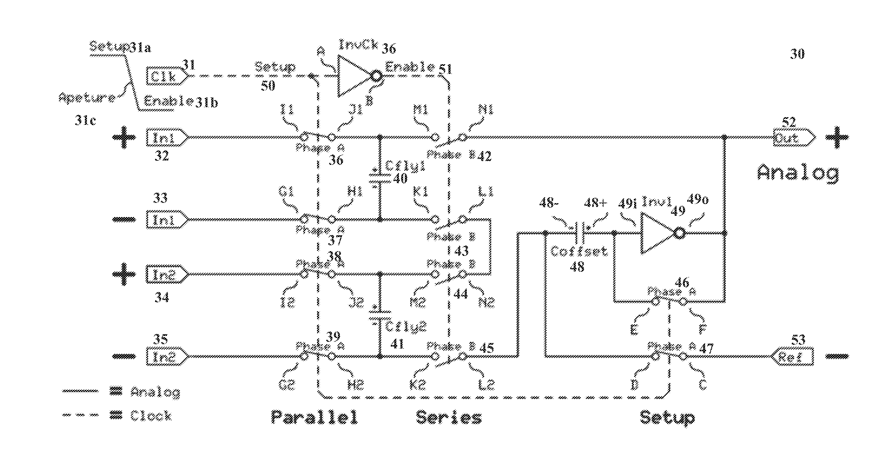
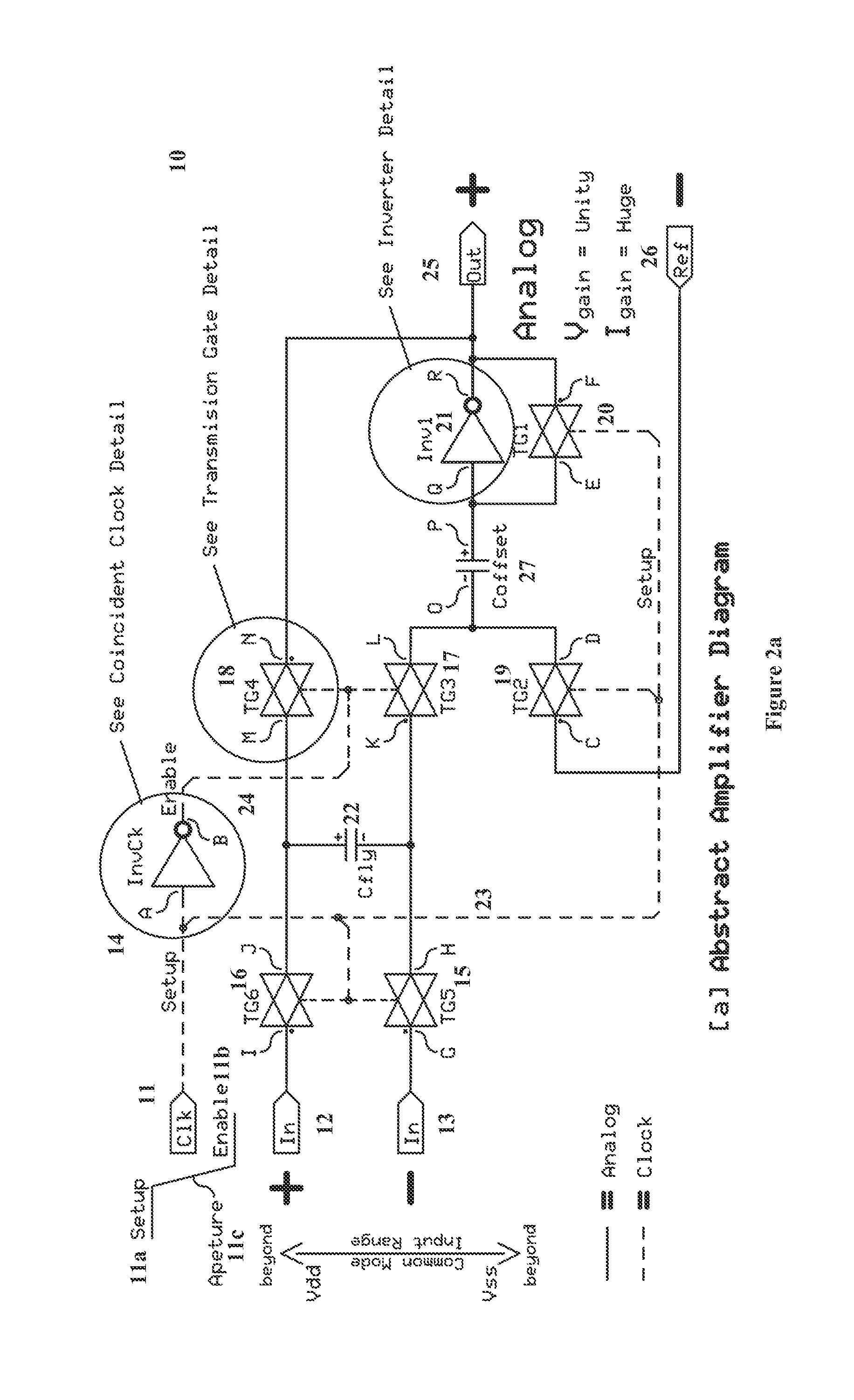
[0037]Analog Amplifier

[0038]An analog amplifier of a preferred embodiment of the present invention utilizes digital parts / components. For example, the central component is a digital inverter. The inverter input (the cause) is the inverse of the inverter output (the effect), therefore when the inverter output is feedback (connected to the inverter input); the inverter input will find equilibrium. This equilibrium will be referred to as the “sweet-spot.” The sweet-spot is the voltage where the inverter has its highest gain and fastest slew rate, thus the greatest sensitivity, and will be somewhere near the center of the power supply rails.

[0039]The output does not necessarily find the sweet spot; it is the input that always determines the sweet-spot. While the sweet-spot is not precise, it can be precisely measured before each operation and stored, for subsequent use during each operation. Changes in the precise voltage of the sweet-spot can be caused by numerous effects including age...


PUM


Abstract

An innovative analog circuit design using digital components is disclosed. Embodiments of the present invention includes, but not limited to analog amplifiers and comparators. An amplifier of an embodiment of the present invention includes an inverter, a plurality of switches, offset capacitor and flying capacitor. The one terminal of the offset capacitor is connected to the input of the inverter. During setup phase of clock signals, the switches are configured to connect input and output of the inverter and to connect the flying capacitor to input terminals of the amplifier, respectively, for storing a differential input voltage. Then, during the enable phase of the clock signals, the switches are configured to connect the first terminal of the second capacitor and the first terminal of the first capacitor, and to connect the second terminal of the second capacitor to the output of the inverter.

Description

CROSS-REFERENCE TO RELATED APPLICATIONS[0001]This application claims priority to U.S. Provisional Patent Application No. 61 / 875,024, filed on Sep. 7, 2013, the disclosure of which is incorporated herein by reference in its entirety.STATEMENT REGARDING FEDERALLY SPONSORED RESEARCH OR DEVELOPMENT[0002]NONE.NAMES OF THE PARTIES TO A JOINT RESEARCH AGREEMENT[0003]NONE.REFERENCE TO A “SEQUENCE LISTING”[0004]NONE.BACKGROUND OF THE INVENTION[0005]1. Field of the Invention[0006]The present invention directs to an innovative analog circuit design using digital components. The present invention further directs to improvements in utilizing semiconductor processing, providing lower noise analog design platforms, allowing lower power supply voltage, higher speed, and fewer component restrictions.[0007]2. Description of Related Art[0008]There is no related art because in the last few years no one has come forward with a solution to making analog in the latest integrated circuit processes. This is...

Claims


Application Information

Patent Timeline
Patent Type & Authority Applications(United States)
IPC IPC(8): H03G1/00H03F3/45
CPCH03G1/0017H03F2203/45101H03F2200/153H03F3/45179
Inventor SCHOBER, ROBERT C.LIKINS, J. DANIEL
Owner SCHOBER ROBERT C
Why Eureka
Try Eureka