Energy management system and fuel saving method for a hybrid electric vehicle

a hybrid electric vehicle and energy management technology, applied in the direction of battery/fuel cell control arrangement, process and machine control, instruments, etc., can solve the problems of energy management system overriding normal control, ess may become fully charged, and the vehicle may be unable to re-start, so as to reduce the electrical charge level of ess, increase anion, and reduce the effect of electrical charge level

Active Publication Date: 2015-03-12
VOLVO LASTVAGNAR AB
View PDF8 Cites 24 Cited by
  • Summary
  • Abstract
  • Description
  • Claims
  • Application Information

AI Technical Summary

Benefits of technology

[0004]It is desirable to provide an inventive energy management system for a hybrid electric vehicle that brings about further improvements with respect to fuel consumption and engine emission, which vehicle comprising an electrical machine for vehicle traction drive and recuperative braking, an electrical storage system ESS for storing recuperated energy, and at least one additional vehicle electrical auxiliary device different from said electrical machine. According to an aspect of the invention, an energy management controller is arranged to, upon establishing a potential for increased amount of recuperated energy during a predicted future downhill descent, direct electrical power from said ESS to said at least one additional electrical auxiliary device for the purpose of reducing the electrical charge level of the ESS, such that an increased amount of energy may be recuperated and stored in said ESS during said predicted future downhill descent.
[0005]According to another aspect of the invention, a fuel saving method for a corresponding hybrid electric vehicle is provided, which method comprises the steps of establishing a potential for increased amount of recuperated energy during a predicted future downhill descent, and subsequently directing electrical power from said ESS to said at least one additional electrical auxiliary device for the purpose of reducing the electrical charge level of the ESS, su

Problems solved by technology

Without the inventive solution, there is a risk that the ESS may become fully charged during a downhill descent, whil

Method used


Image

  • Energy management system and fuel saving method for a hybrid electric vehicle
  • Energy management system and fuel saving method for a hybrid electric vehicle
  • Energy management system and fuel saving method for a hybrid electric vehicle

Examples


Embodiment Construction

[0021]Various aspects of the invention will hereinafter be described in conjunction with the appended drawings provided to illustrate and not to limit the invention, wherein like designations denote like elements, and variations of the aspects are not restricted to the specific, shown aspect, but are applicable on other variations of the invention.

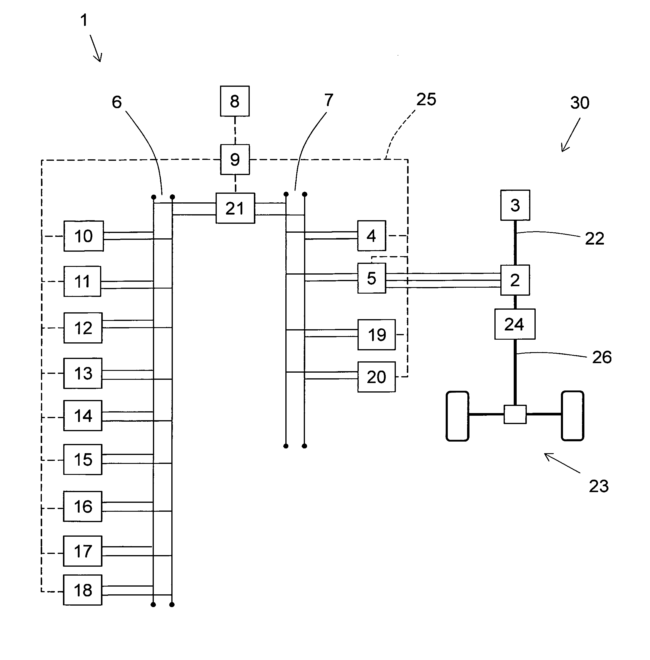
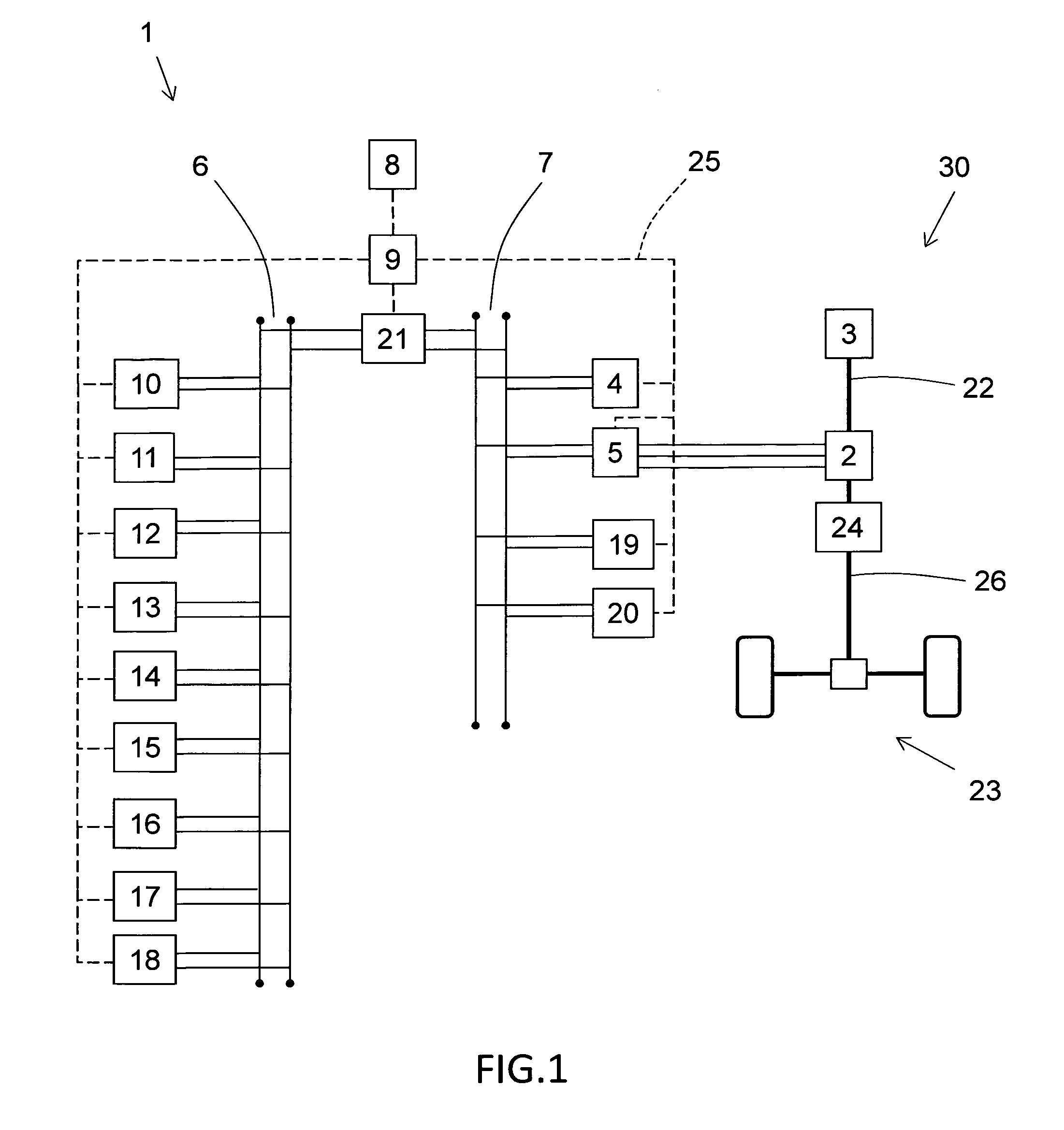
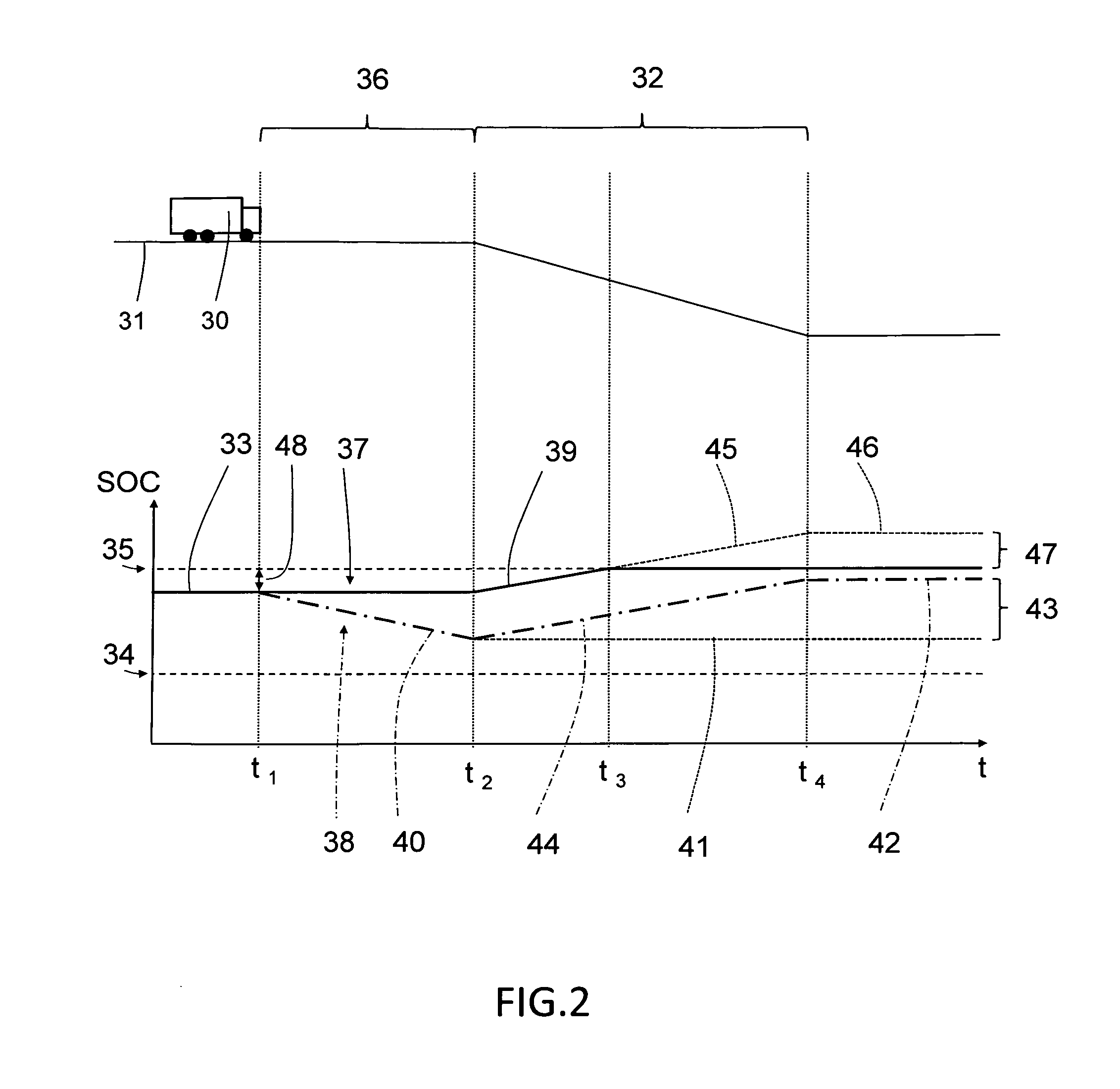
[0022]FIG. 1 shows an example of a schematic system design used for implementing the inventive energy management system 1. The energy management system 1 is designed for use in hybrid electric vehicles HEV, which in general are characterised by their drive train that has combined propulsion by means of an electrical machine 2, as well as a combustion engine 3. The disclosed inventive embodiment shows a parallel hybrid drive train system, in which the combustion engine 3 is rotatably connectable and disconnectable to the electrical machine 2 via a first drive shaft 22. The electrical machine 2 is subsequently rotatably connected to the rear...


PUM


Abstract

An energy management system is provided for a hybrid electric vehicle including an electrical machine for vehicle traction drive and recuperative braking, an electrical storage system ESS for storing recuperated energy, and at least one additional vehicle electrical auxiliary device different from the electrical machine. An energy management controller is arranged to, upon establishing a potential for increased amount of recuperated energy during a predicted future downhill descent, direct electrical power from the ESS to the at least one additional electrical auxiliary device for the purpose of reducing the electrical charge level of the ESS, such that an increased amount of energy may be recuperated and stored in the ESS during the predicted future downhill descent.

Description

BACKGROUND AND SUMMARY[0001]The present invention relates to an energy management system for a hybrid electric vehicle that comprises an electrical machine for vehicle traction drive and recuperative braking, an electrical storage system for storing recuperated energy, and at least one additional vehicle electrical auxiliary device different from said electrical machine. The present invention further relates to a fuel saving method for said hybrid electric vehicle.[0002]The overall aim of energy management systems for hybrid electric vehicles is to manage electrical power consumption and power recuperation to lower overall fuel consumption and emissions, and improving vehicle drivability.[0003]Document US 2005 / 0274553 A1 shows a predictive energy management system for hybrid electric vehicles which, based on predicted driving cycles and terrain, selects a power command to operate an electric motor and an engine for the purpose of achieving better fuel economy and lower emissions. Fu...

Claims


Application Information

Patent Timeline
IPC IPC(8): B60W30/18B60L11/18B60W40/076B60W10/26B60W10/30B60L7/16B60W20/00
CPCB60W30/18127B60L7/16B60L11/1861B60W40/076B60W10/26B60W10/30B60W20/00B60W10/08B60W50/0097B60W2510/244B60W2710/244B60W2710/305B60W2552/20B60W2556/50B60W20/14B60L58/12Y02T10/70Y02T10/84
Inventor LENNEVI, JERKERAXELSSON, TOBIAS
Owner VOLVO LASTVAGNAR AB
Why Eureka
Try Eureka