Phosphor, LED Light-Emission Element, and Light Source Device

a technology of led light-emitting elements and phosphors, which is applied in the field of phosphors, can solve the problems of restricted use of cd, achieve the effects of suppressing the reaction of (ca), improving moisture resistance, and suppressing the reaction of dissimilar materials with each other

Active Publication Date: 2015-03-19
MITSUI MINING & SMELTING CO LTD
View PDF2 Cites 7 Cited by
  • Summary
  • Abstract
  • Description
  • Claims
  • Application Information

AI Technical Summary

Benefits of technology

[0021]The CaS-based phosphor suggested by the present invention includes a host material represented by composition formula: Ca1-xSrxS.yZnO (wherein 0≦x<1, and 0<y≦0.5), and is composed of, for example, (Ca,Sr)S and (Ca,Sr)ZnOS compositized together. When the CaS-based phosphor suggested by the present invention is heated together with a dissimilar material, since (Ca,Sr)ZnOS exhibits a buffering action and works to suppress the reaction of (Ca,Sr)S, this (Ca,Sr)S and the dissimilar material reacting with each other can be suppressed. Accordingly, for example, even if the phosphor suggested by the present invention is heated together with a glass composition, since the phosphor reacting with the glass composition can be prevented, a homogeneous glass film can be formed on the phosphor particle surface, and moisture resistance can be improved. Furthermore, since luminescence characteristics can be maintained at that time, the CaS-based phosphor of the present invention can be suitably used in, for example, phosphors and light-emission elements used in light source devices such as white LED light sources, vacuum fluorescent displays (VFD), field emission displays (FED), and electroluminescence (EL), and light source devices.

Problems solved by technology

However, the use of Cd has been restricted due to environmental problems, and the like, and new red phosphors that do not contain Cd have been developed.

Method used


Image

  • Phosphor, LED Light-Emission Element, and Light Source Device
  • Phosphor, LED Light-Emission Element, and Light Source Device
  • Phosphor, LED Light-Emission Element, and Light Source Device

Examples


example 1-1

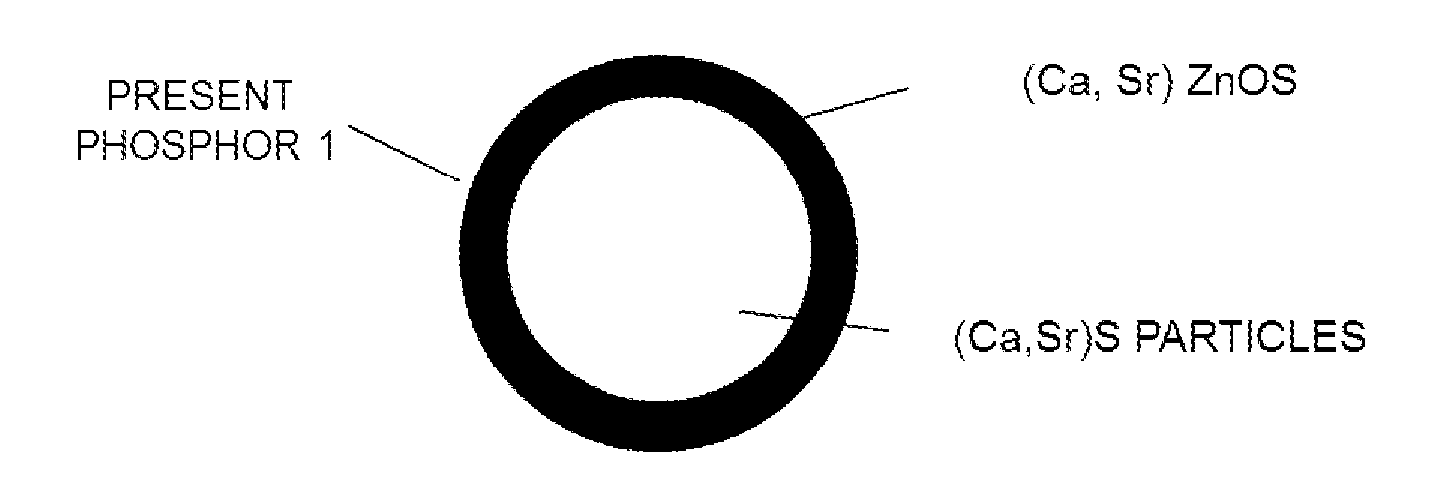
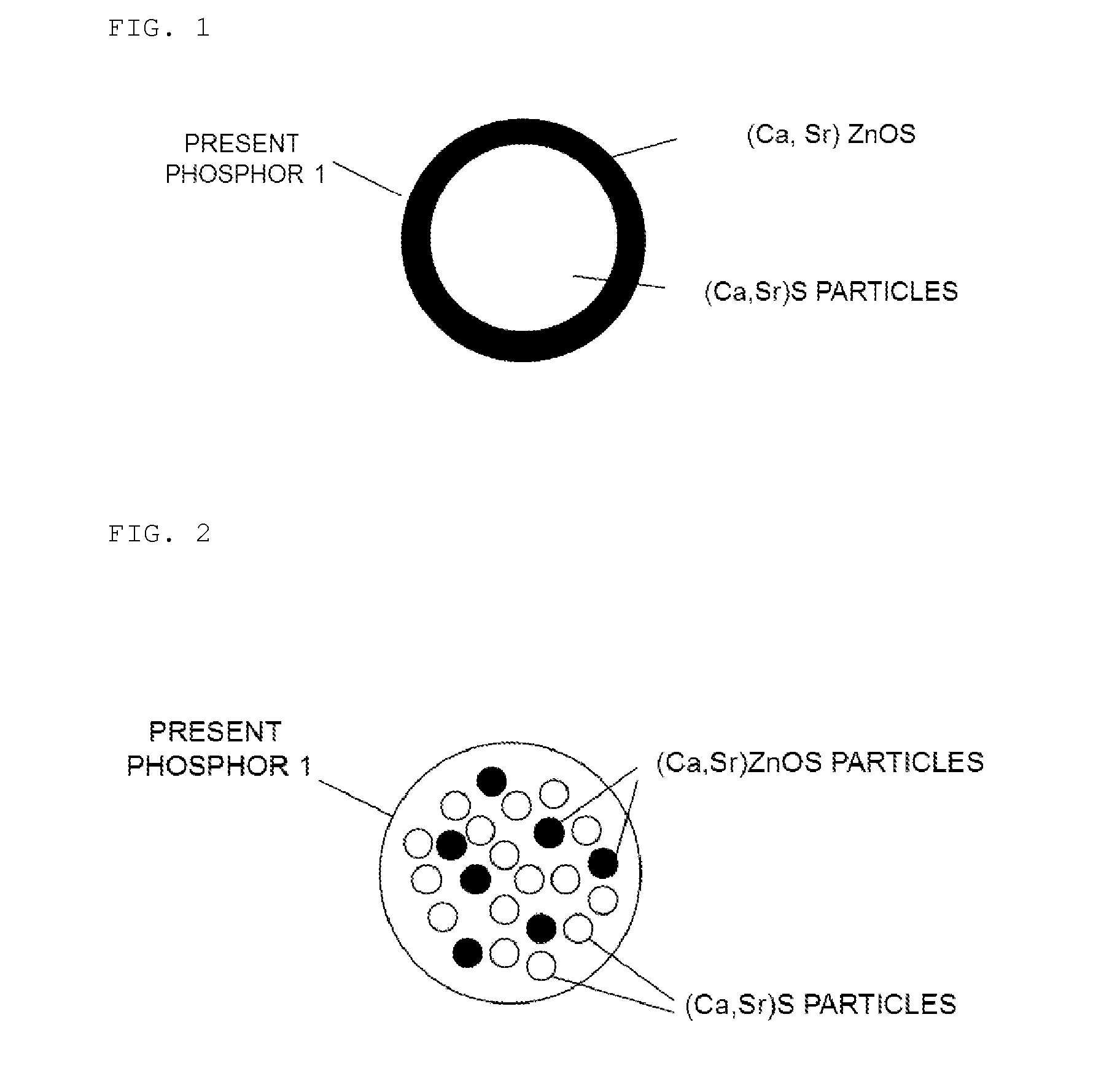
[0143]A CaS powder, a SrS powder, a EuF3 powder, and a ZnO powder as raw materials were respectively weighed to obtain a mass ratio of 13.00:86.25:0.75:20, and these were introduced into deionized water. The mixture was subjected to pulverization and mixing using a bead mill, and to a drying treatment, and then the mixture was calcined at 900° C. for 4 hours in an argon gas atmosphere. Thus, a phosphor powder (sample) represented by compositional formula: Ca1-xSrxS.yZnO:Eu (wherein x=0.8, y=0.27, and Eu: 0.4 mol %) was obtained.

[0144]This phosphor powder thus obtained was identified using an X-ray diffraction apparatus, and peaks of the (Ca,Sr)ZnOS phase and the ZnS phase were recognized.

example 1-2

[0145]A phosphor powder (sample) represented by compositional formula: Ca1-xSrxS.yZnO:Eu (wherein x=0.8, y=0.27, and Eu: 0.4 mol %) was obtained in the same manner as in Example 1-1, except that a Eu2O3 powder was used instead of the EuF3 powder.

example 1-3

[0146]A phosphor powder (sample) represented by compositional formula: Ca1-xSrxS.yZnO:Eu (wherein x=0.8, y=0.27, and Eu: 0.4 mol %) was obtained in the same manner as in Example 1-1, except that a Eu2(C2O4)3 powder was used instead of the EuF3 powder.


PUM

PropertyMeasurementUnit
emission wavelengthsaaaaaaaaaa

Abstract

Provided is a novel CaS-based phosphor with which chemical reactions can be inhibited even if said CaS-based phosphor is heated with a heterogeneous material. This phosphor includes: a crystalline parent material represented by the composition formula Ca1-xSrxS.yZnO (in the formula, 0≦x<1, 0<y≦0.5); and a luminescent center.

Description

TECHNICAL FIELD[0001]The present invention relates to a phosphor, and more particularly, the invention relates to a phosphor that can be used in light source apparatuses such as a white LED light source device, a vacuum fluorescent display (VFD), a field emission display (FED), and electroluminescence (EL), an LED light-emission element using the phosphor, and a light source device.BACKGROUND ART[0002]In the past, ZnCdS:Ag,Cl phosphor and the like have been mainly used as red phosphors, for the reason of being chemically stable or the like. However, the use of Cd has been restricted due to environmental problems, and the like, and new red phosphors that do not contain Cd have been developed.[0003]For example, Patent Document 1 and Patent Document 2 disclose red phosphors containing calcium sulfide as a host material, Eu as a luminescent center (activator), and Mn, Li, Cl, Ce, Gd or the like as a sensitizer (co-activator).[0004]Furthermore, Patent Document 3 discloses, as a red phosp...

Claims


Application Information

Patent Timeline
Patent Type & Authority Applications(United States)
IPC IPC(8): C09K11/02H01L31/055H01L33/50C09K11/77
CPCC09K11/025C09K11/7731H01L33/502H01L33/507H01L31/055Y02E10/52
Inventor INAMURA, MASAAKIINOUE, MICHIYOKUMAGAI, AKINORISHIMIZU, HARUKAMORI, TAKAYOSHIITOH, JUN-ICHI
Owner MITSUI MINING & SMELTING CO LTD
Why Eureka
Try Eureka