System for enhanced reclaimed water recovery

a reclaimed water and enhanced technology, applied in the field of water purification and reclamation, can solve the problems of resistance of fracking companies, difficult treatment of wastewater, and use of conventional methods, and achieve the effects of reducing the rate of final waste generation, increasing the overall reclaimed water recovery, and maintaining the quality of reclaimed water

Inactive Publication Date: 2015-03-26
PACIFIC ADVANCED CIVIL ENG
View PDF3 Cites 8 Cited by
  • Summary
  • Abstract
  • Description
  • Claims
  • Application Information

AI Technical Summary

Benefits of technology

[0009]The high TDS wastewater is first treated by a solid-oil-water separation apparatus such as one or more electrochemical reactor(s) where electrochemically generated low-solubility metal cations such as aluminum (Al3+) and ferrous iron (Fe2+) and their oxides and hydroxides aid the separation of suspended solids and oil droplets from water, which is further treated by a low pressure membrane filtration apparatus to remove majority of divalent cations and divalent anions and organic matter, as well as some of monovalent ions. A fraction of concentrate stream from the low-pressure membrane filtration apparatus is sent back to the electrochemical reactor(s) and the remainder of the concentrate stream is wasted. A low-pressure membrane filtration concentrate may contain high levels of divalent cations and anions along with monovalent cations and anions originally present in the aqueous medium to be treated. The divalent cations may be precipitated in the solid-oil-water separation apparatus by electrochemically generate

Problems solved by technology

These wastewaters are difficult to treat because of the very high salinity, which prohibits the use of conventional approaches such as reverse osmosis (RO) to remove undesirable constituents and recover reusable water.
However, as many of these fracking operations take place in dry and/or remote areas that do not have easy access to a large volume of water, fracking companies face resistance from other special interests, as the addition of a new water user is undesirable to the local community.
This is a desirable possibility, but the water reuse poses some challenges.
These wastewaters are generally unsuitable for re-injection for fracking as is because they contain high levels of constituents like dissolved ions, emulsified colloids, hydrocarbons, oil and grease, silt,

Method used


Image

  • System for enhanced reclaimed water recovery
  • System for enhanced reclaimed water recovery

Examples


working examples

NON-LIMITING WORKING EXAMPLES

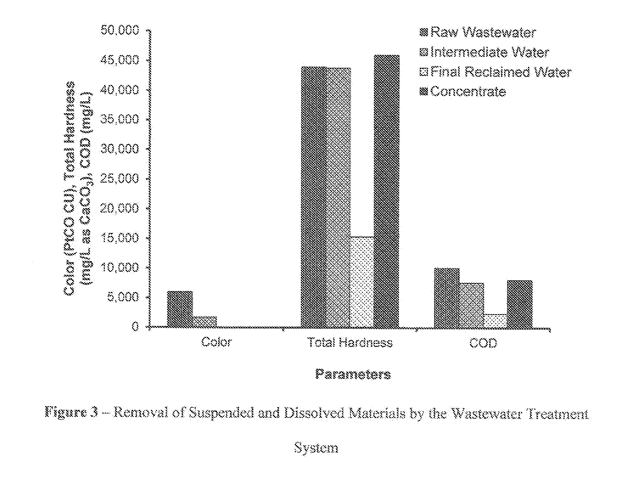
[0023]The following example illustrates one embodiment of the invention. The parameters of color, total hardness, and chemical oxygen demand (COD) are presented in FIG. 3.

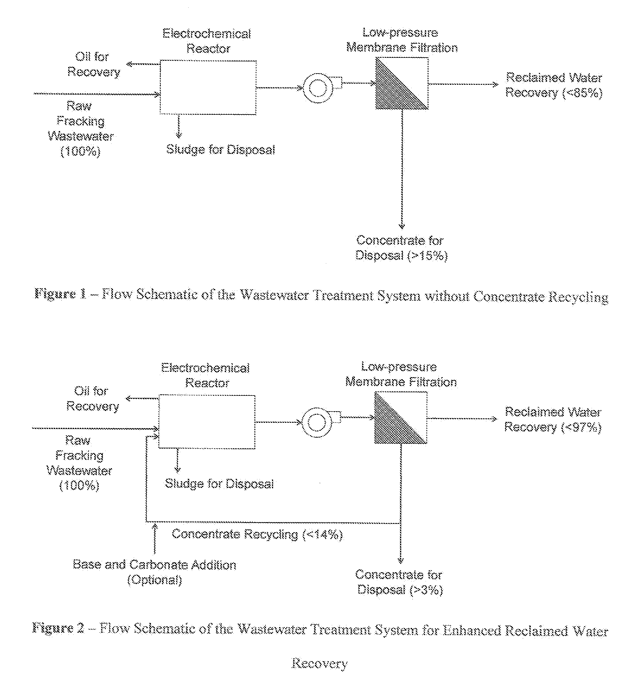
[0024]A produced water sample obtained from a fracking operation in the Midwestern United States was treated by a semi-batch wastewater treatment system. The initial concentrations of TDS, total hardness, alkalinity, and COD were 293,000, 44,000, 360, and 10,100 mg / L, respectively, while initial values of pH and color (platinum-cobalt color scale (Pt—Co) color units) were 5.4 and 6,000, respectively. The experiment was conducted at temperature=24 to 26° C. FIG. 3 shows the removal, of suspended and dissolved materials by the method described above. The overall reclaimed water recovery was approximately 80% with concentrate recycling, whereas the recovery was 70% without recycling.


PUM

PropertyMeasurementUnit
Fractionaaaaaaaaaa
Pressureaaaaaaaaaa
Chemical propertiesaaaaaaaaaa

Abstract

An apparatus for treating wastewater, such as high-solids contend wastewater from a fracking operation, includes a solids-oil-water separation apparatus coupled to a low-pressure membrane filtration apparatus, with a wastewater recycling conduit coupled at one end to the low-pressure membrane filtration apparatus and coupled at a second end to the solids-oil-water separation apparatus, whereby progressive recycling of membrane concentrate from the low-pressure membrane filtration apparatus through the wastewater recycling conduit, into the solids-oil-water separation apparatus, provides recovery of as much as 97% of the water from a raw wastewater stream.

Description

CROSS-REFERENCE TO RELATED APPLICATION[0001]This application claims the benefit of U.S. provisional application No. 61 / 882,252, filed Sep. 25, 2013, the entire contents of which are incorporated herein by this reference.FIELD OF THE INVENTION[0002]This invention is related to water purification and reclamation, in which contaminated water is treated by a series of unit processes, such as physical, chemical, and biological treatment processes, to recover reusable water.BACKGROUND OF THE INVENTION[0003]Operation of certain processes generates wastewaters having high to very high levels of dissolved inorganic substances and salinity. These wastewaters are difficult to treat because of the very high salinity, which prohibits the use of conventional approaches such as reverse osmosis (RO) to remove undesirable constituents and recover reusable water. One example of such processes is hydraulic fracturing, which is also called hydrofracturing or fracking. Fracking is a technique utilized b...

Claims


Application Information

Patent Timeline
IPC IPC(8): C02F1/44B01D61/08C02F1/463B01D21/00C02F1/40C02F1/465
CPCC02F1/442C02F1/40C02F1/465C02F1/463B01D21/0009B01D21/0084C02F2301/046C02F2101/32C02F2103/10C02F2201/461C02F2209/07C02F2209/08B01D61/08C02F1/66C02F2209/05C02F2209/06C02F2209/10C02F2209/11C02F2209/22B01D61/027B01D2311/04B01D2311/25B01D2311/2684B01D2311/252
Inventor KOMOR, ANDREW T.IKEHATA, KEISUKE
Owner PACIFIC ADVANCED CIVIL ENG
Why Eureka
Try Eureka