
Detection circuit for detecting signal amplitude

Active Publication Date: 2015-03-26
SUMITOMO ELECTRIC IND LTD
View PDF2 Cites 2 Cited by
  • Summary
  • Abstract
  • Description
  • Claims
  • Application Information

AI Technical Summary

Benefits of technology

The present invention provides a detection circuit that can detect the peak value and amplitude of an input differential signal or signal. It includes a differential circuit, a hold capacitor, a level sensing circuit, and a switch. The circuit can generate a hold potential based on the peak value and sense the voltage level of the input signal. The switch can connect or disconnect the output terminal to a second current source based on the switching signal. The technical effect is that the detection circuit can accurately detect the peak value and amplitude of the input signal and improve the accuracy of signal detection.

Problems solved by technology

In addition, since an input offset value of the operational amplifier causes an error of a peak detection value, the gain of the operational amplifier is required to be maintained to be high up to a high frequency in order to decrease the error.
Therefore, the peak detection circuit described in the patent document 1 described above is not appropriate for peak detection of a signal with a high frequency.
That is, a ratio of on-time when an input signal is close to a peak value of it with respect to off-time when the input signal is lower away from the peak value becomes small, and thus an error of the detected amplitude tends to be degraded.

Method used


Image

  • Detection circuit for detecting signal amplitude
  • Detection circuit for detecting signal amplitude
  • Detection circuit for detecting signal amplitude

Examples


Embodiment Construction

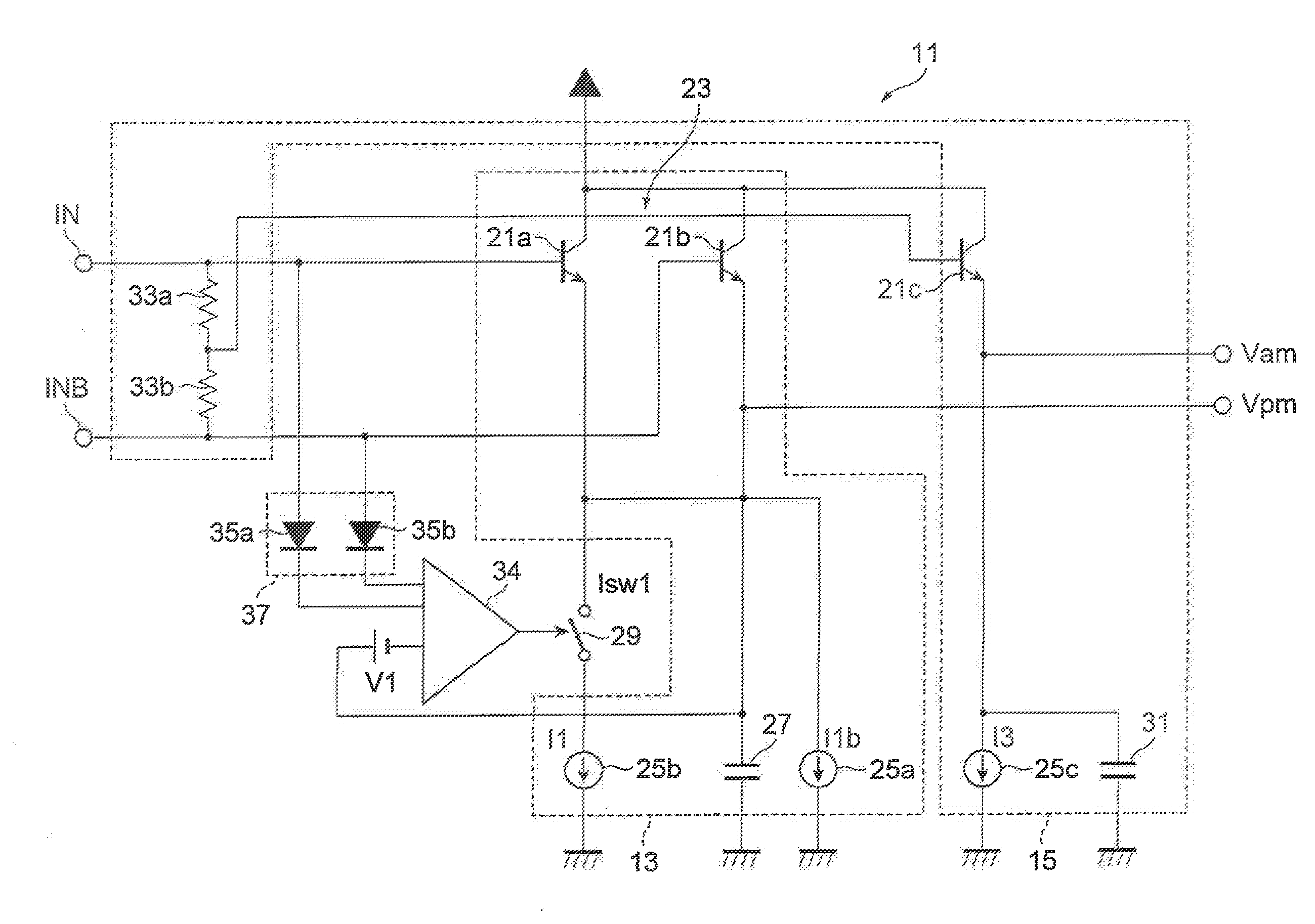
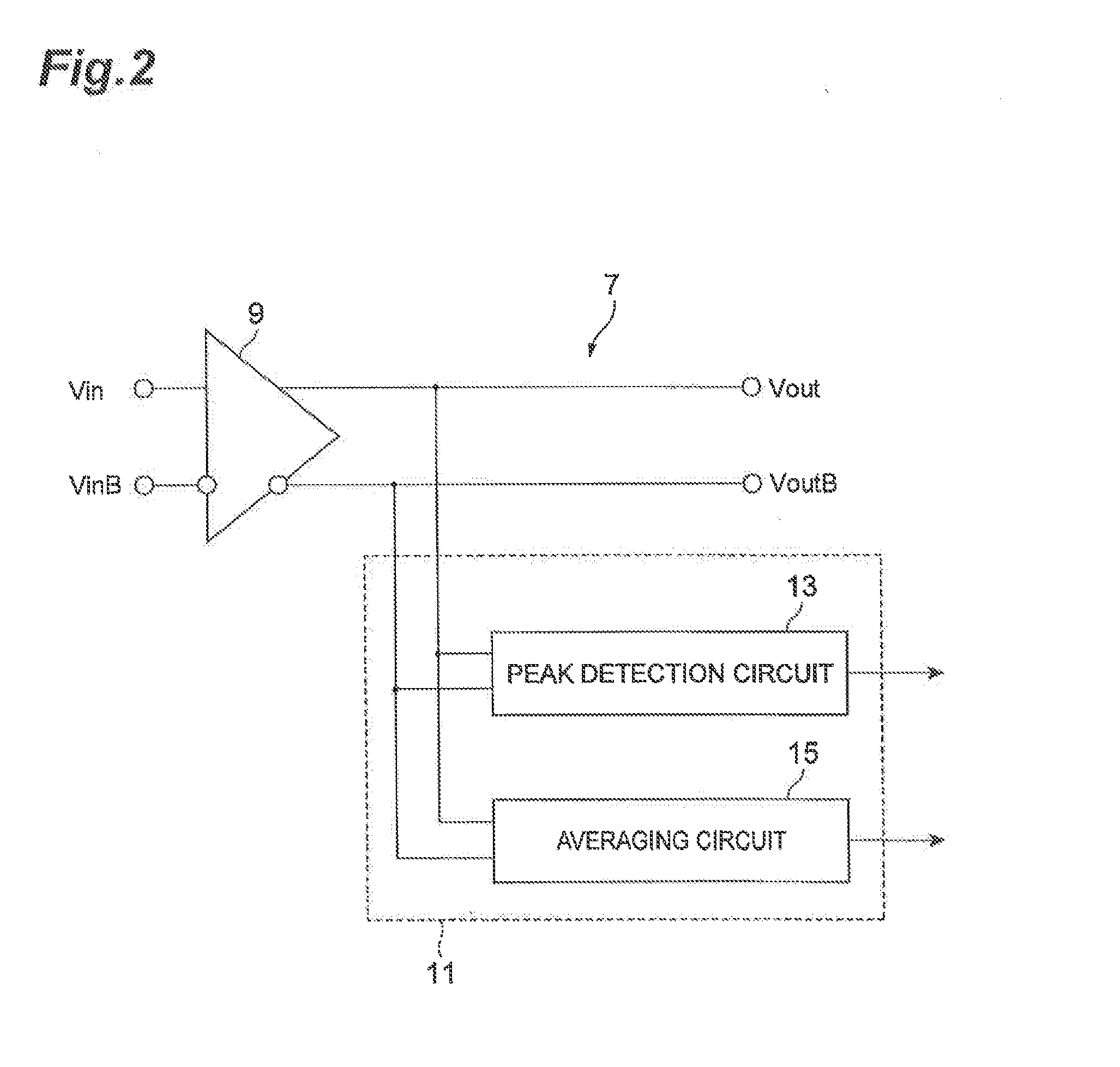
[0027]A detection circuit according to an aspect of the present invention configured to detect a peak value of an input differential signal and detect an amplitude of the input differential signal based on the peak value, includes a differential circuit including a pair of differential transistors configured to receive the input differential signal and a first current source, the pair of the differential transistors having a common output terminal connected to the first current source, a hold capacitor connected between the common output terminal and a reference potential for generating a hold potential corresponding to the peak value, a level sensing circuit configured to sense a voltage level of the input differential signal and output a switching signal based on the voltage level; and a switch configured to receive the switching signal and electrically connect the common output terminal and a second current source when the switching signal exceeds a threshold level being lower th...


PUM


Abstract

A detection circuit includes a differential circuit including a pair of differential transistors configured to receive the input differential signal and a first current source, the pair of the differential transistors having a common output terminal connected to the first current source, a hold capacitor connected between the common output terminal and a reference potential for generating a hold potential, a level sensing circuit configured to sense a voltage level of the input differential signal and output a switching signal, and a switch configured to receive the switching signal and electrically connect the common output terminal and a second current source when the switching signal exceeds a threshold level being lower than the hold potential by a predetermined amount, and electrically disconnect the common output terminal and the second current source when the switching signal stays lower than the threshold level.

Description

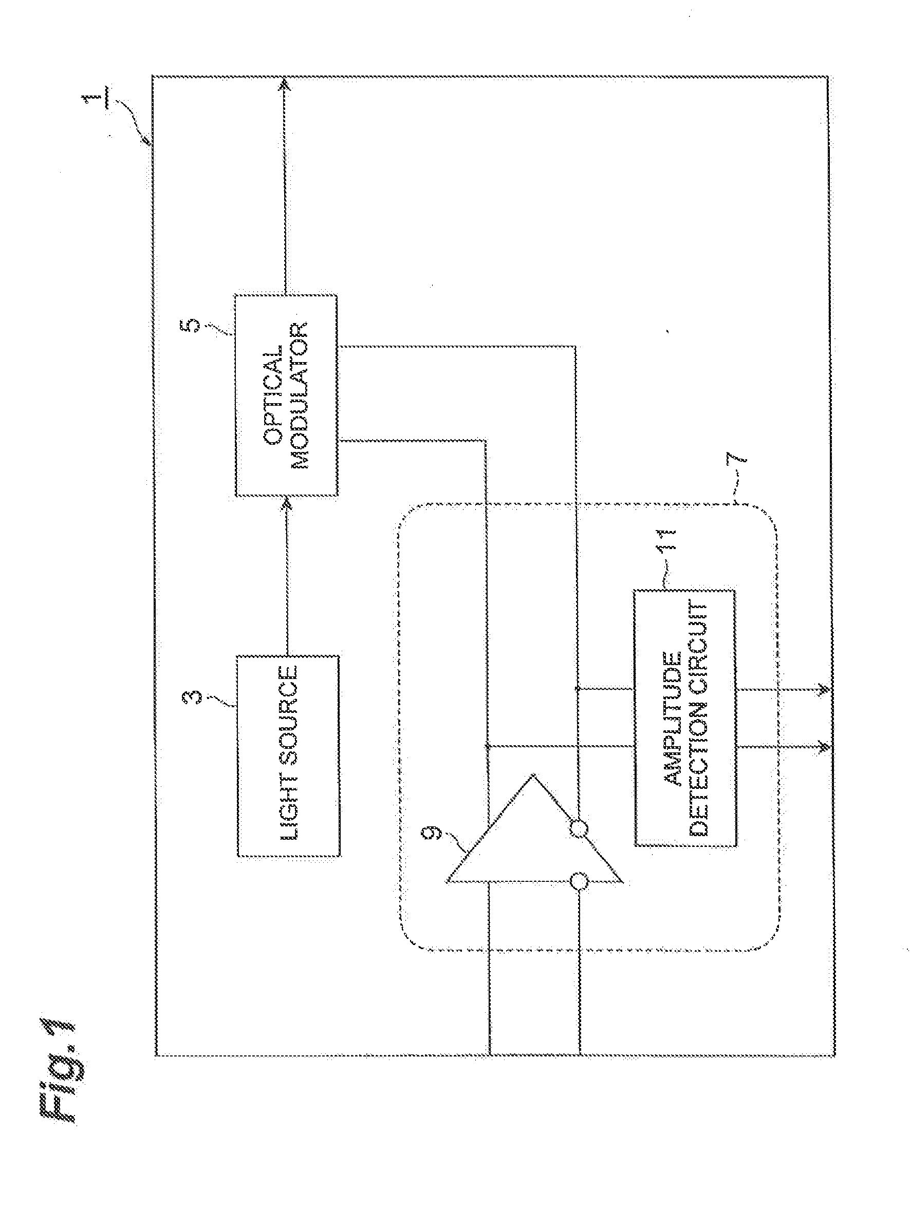
BACKGROUND OF THE INVENTION[0001]1. Field of the Invention[0002]The present invention relates to a detection circuit for detecting signal amplitude.[0003]2. Related Background of the Invention[0004]An optical transmitter module used for an optical communication is configured by a light source such as a laser diode, an optical modulator such as an electro-absorption modulator (EAM) or a Mach-Zehnder modulator (MZM), and a modulator driving circuit. In addition, a detection circuit for detecting an amplitude of a driving signal to drive the optical modulator is sometimes added to the modulator driving circuit. With respect to the detection circuit used in the optical transmitter module for high-speed communication of 32 Gbps or 40 Gbps, high-speed detection is required because a communication signal has a high frequency component up to approximately 10 GHz. In addition, in a multi-level modulation method such as pulse amplitude modulation 4 (PAM4) or 16 quadrature amplitude modulation...

Claims


Application Information

Patent Timeline
IPC IPC(8): H03K5/125
CPCH03K5/125
Inventor TATSUMI, TAIZO
Owner SUMITOMO ELECTRIC IND LTD
Learn More