
Microscope super-resolution illumination source

Inactive Publication Date: 2015-03-26
L J TECH
View PDF4 Cites 3 Cited by
  • Summary
  • Abstract
  • Description
  • Claims
  • Application Information

AI Technical Summary

Benefits of technology

The patent describes a portable microscope that uses a special illumination to observe tiny objects. The microscope has a unique arrangement of light sources that emit light in both the visible and infrared frequencies. The microscope system can be used with a conventional optical microscope for direct observation of small objects. The microscope SRI apparatus has a light source array consisting of individual sources distributed in the internal surface of a housing, which is powered and controlled by an electronic circuit. The microscope SRI apparatus can be adapted to emit light in different frequency ranges and can have a cylindrical, paraboloid, elliptical, or flat screen shape. The technical effects of this patent include improved resolution for observing small objects and a more flexible and versatile microscope system.

Problems solved by technology

However, all the above-mentioned optical imaging techniques require either special sample fabrication or intensive numerical image post-processing.

Method used


Image

  • Microscope super-resolution illumination source
  • Microscope super-resolution illumination source
  • Microscope super-resolution illumination source

Examples


Embodiment Construction

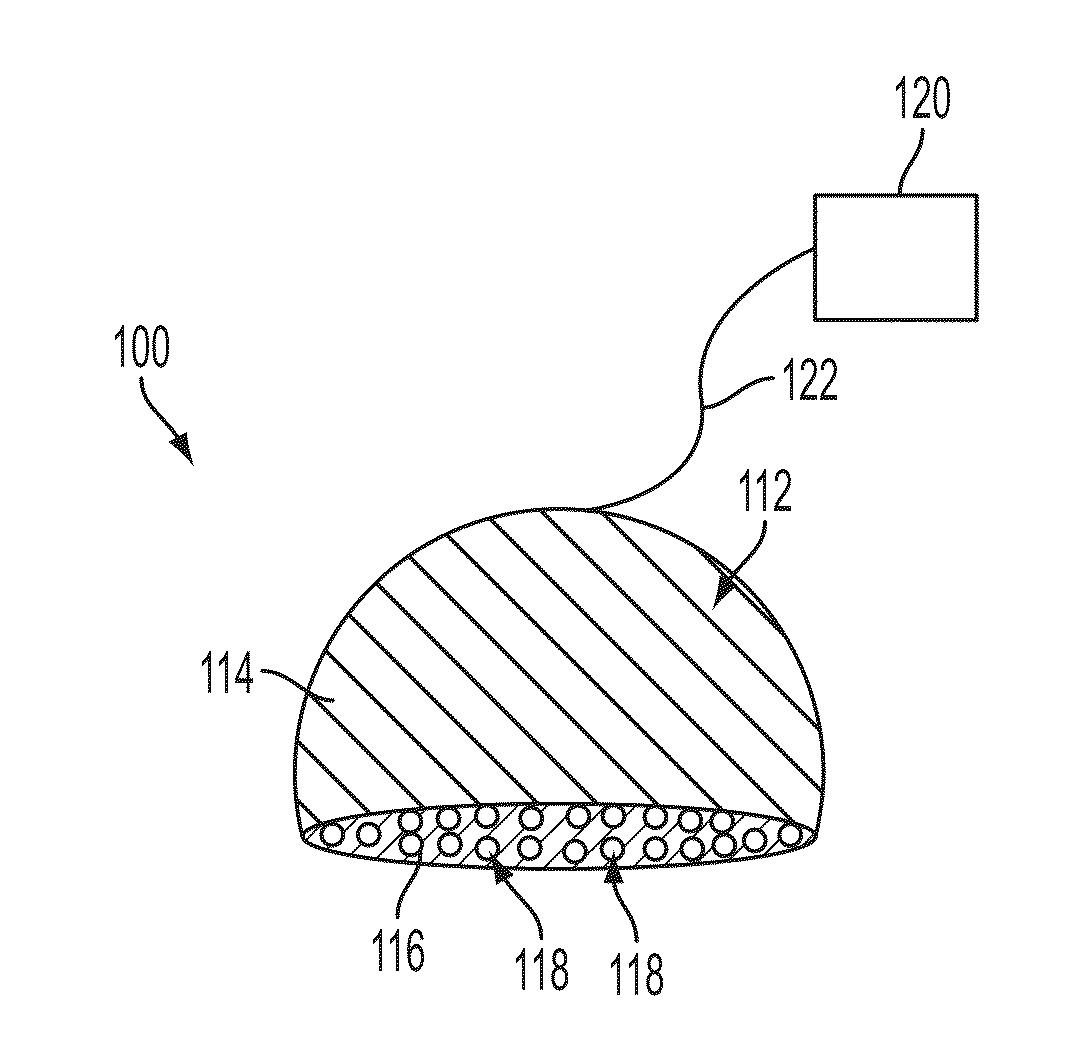
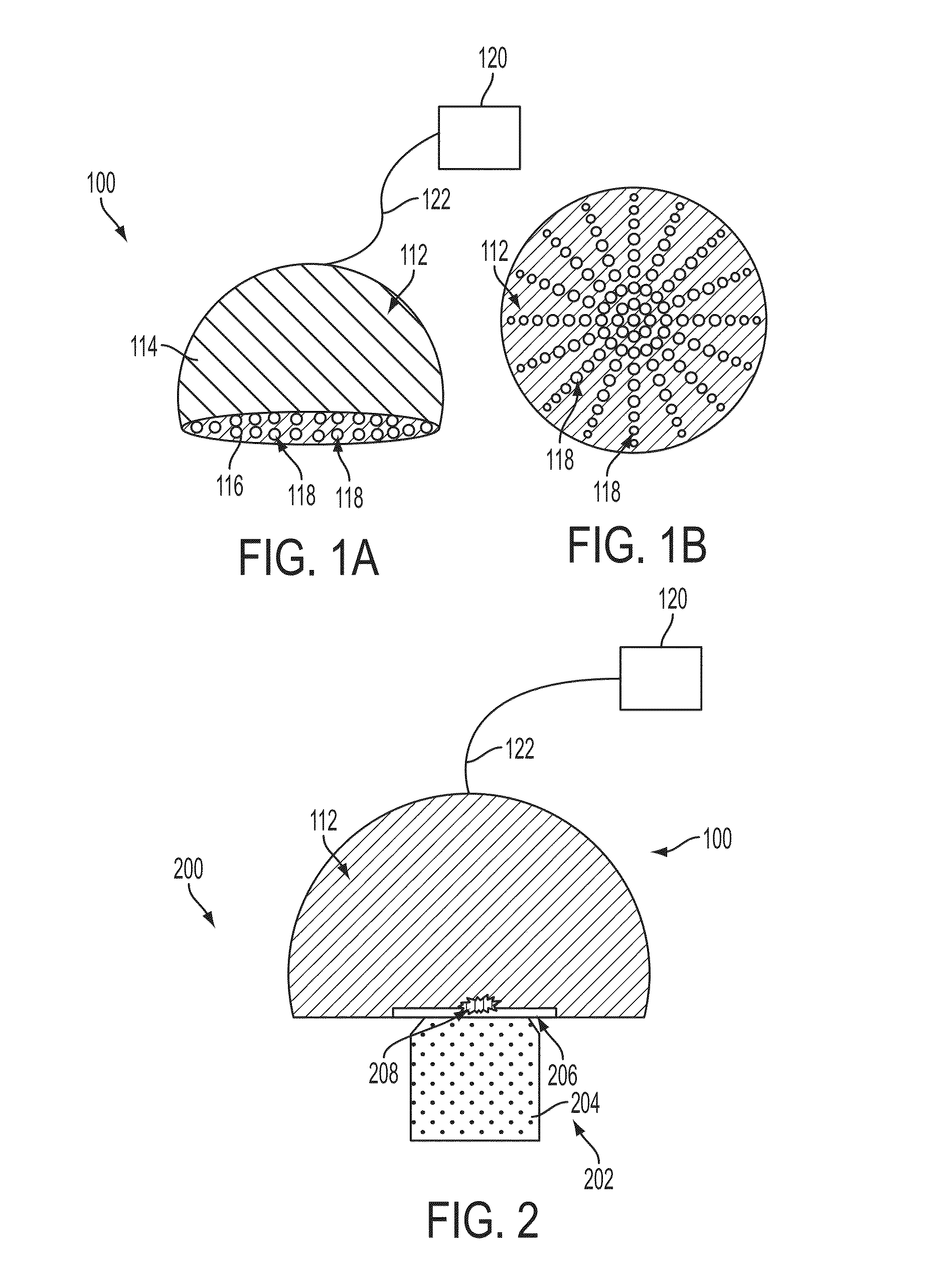
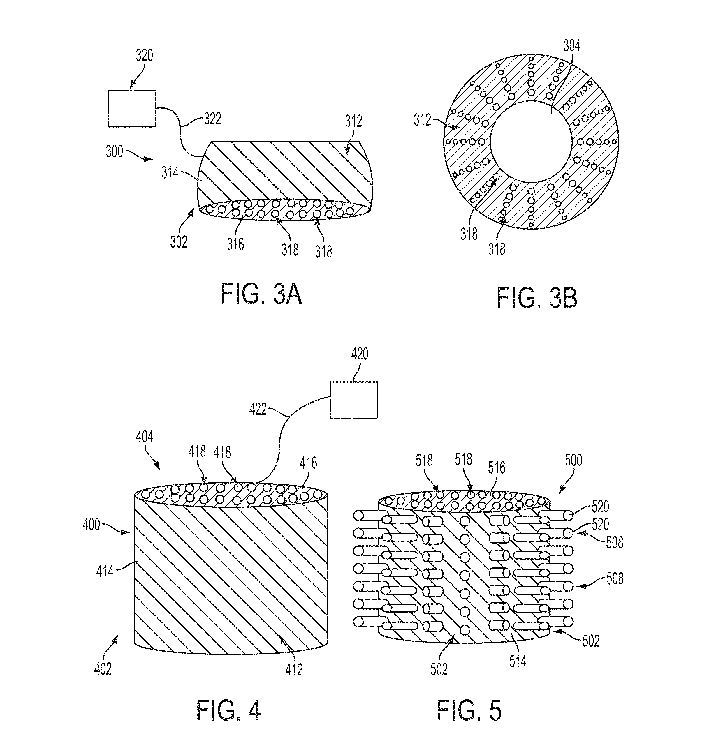
[0024]Embodiments of the present invention provide an alternative super-resolution illumination apparatus for use with conventional optical microscopes. In accordance with an embodiment of the present invention, a portable microscope super-resolution illumination (SRI) apparatus includes a two-dimensional (2D) array of individual sources of radiation distributed on the internal surface of a housing body. The microscope SRI apparatus further includes a power supply having an electronic circuit adapted to power and to control the array of individual sources of radiation. In one aspect of this embodiment, the individual sources of the microscope SRI apparatus emit radiation in the visible frequency range of the spectrum. In another aspect of this embodiment, the individual sources of the microscope SRI apparatus emit radiation in the infrared frequency range of the spectrum. In another embodiment, a super-resolution microscope system can be provided. The super-resolution illumination (...


PUM


Abstract

An alternative illumination source for traditional optical microscopes is provided. This super-resolution illumination source permits to use a traditional optical microscope for the direct observation of objects smaller than 100 nanometers such as subcellular structures in microorganisms, carbon nanotubes and other nanosize objects, and even nanostructures fabricated on top of a silicon wafer. This invention relies on the integration of two functional elements: a microscope, and the super-resolution illumination source. The super-resolution illumination source is formed by an array of light emitting diodes (LEDs) uniformly distributed in a hemisphere. The object under observation is illuminated by the light emitted in all directions by the array of LEDs. Real, wide-field images of the sample with nano-resolution are direct and analogically formed by the microscope's lenses, without the need of sample tagging, intensive computation or scanning. Depending on the wavelength emission of the LEDs, nano-resolution can be obtained with ultraviolet, infrared, and visible illumination.

Description

BACKGROUND OF THE INVENTION[0001]1. Field of the Invention[0002]The disclosure relates generally to illumination sources and more specifically, to alternative illumination sources for traditional optical microscopes.[0003]2. Description of the Related Art[0004]Traditional microscopy is diffraction-limited to spatial periods (p) larger than ˜λ / NA or separation between two points (Δx) larger than ˜0.5 to 0.8 times λ / NA where λ is the free space wavelength of the illuminating radiation and NA is the numerical aperture of the microscope's objective lens (see for instance the following publications: Feynman R P, Leighton R B, Sands M, The Feynman Lectures on Physics, Addison-Wesley, Mass., Sixth Edition, Vol. I, pages 30-(1-5), 1977; Hecht E, Optic, Addison Wesley, Mass., Third Edition, pages 439-472, 1998; Born M, and Wolf E, Principles of Optics, Pergamon Press, Oxford, Fifth Edition, pages 418-424, 1975; Durant S, Liu Z, Steele J M, Zhang X, Theory of the transmission properties of an...

Claims


Application Information

Patent Timeline
IPC IPC(8): G02B21/06
CPCG02B21/06G02B21/16
Inventor MOLINA, LUIS
Owner L J TECH
Learn More