Back-up boiler system for a solar thermal power plant based on molten salt technology, a solar thermal power plant and a method for operating a solar thermal power plant
a solar thermal power plant and boiler system technology, applied in the direction of solar heat generation, steam superheaters, lighting and heating apparatus, etc., can solve the problems of reducing the efficiency of the cycle to convert steam into electricity, reducing the efficiency of the cycle, and limiting the operation of known solar thermal power plants. , to achieve the effect of maximizing the capacity of electricity for sale, minimizing the use of electricity, and minimizing the downtim
- Summary
- Abstract
- Description
- Claims
- Application Information
AI Technical Summary
Benefits of technology
Problems solved by technology
Method used
Image
Examples
first embodiment
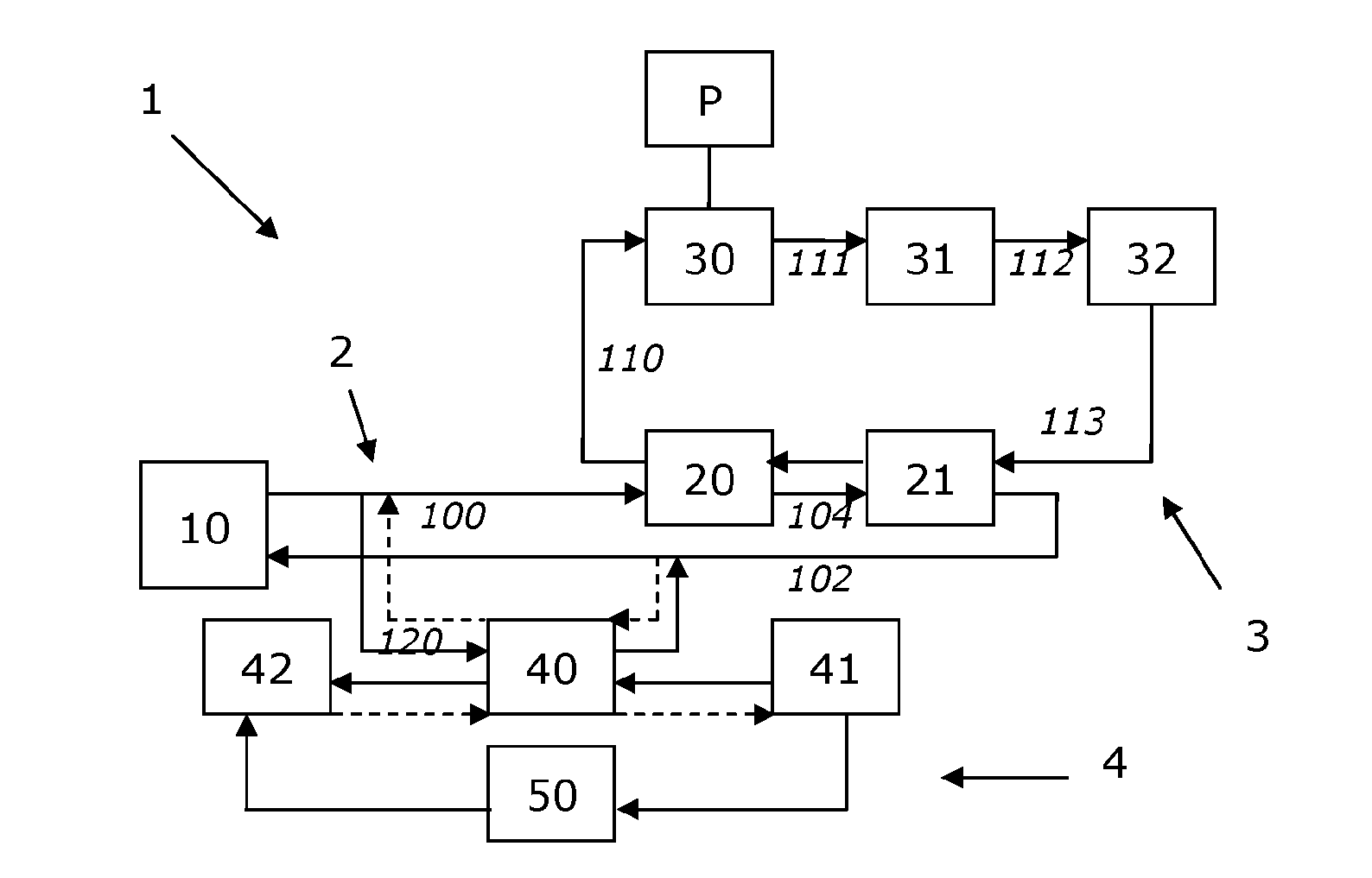
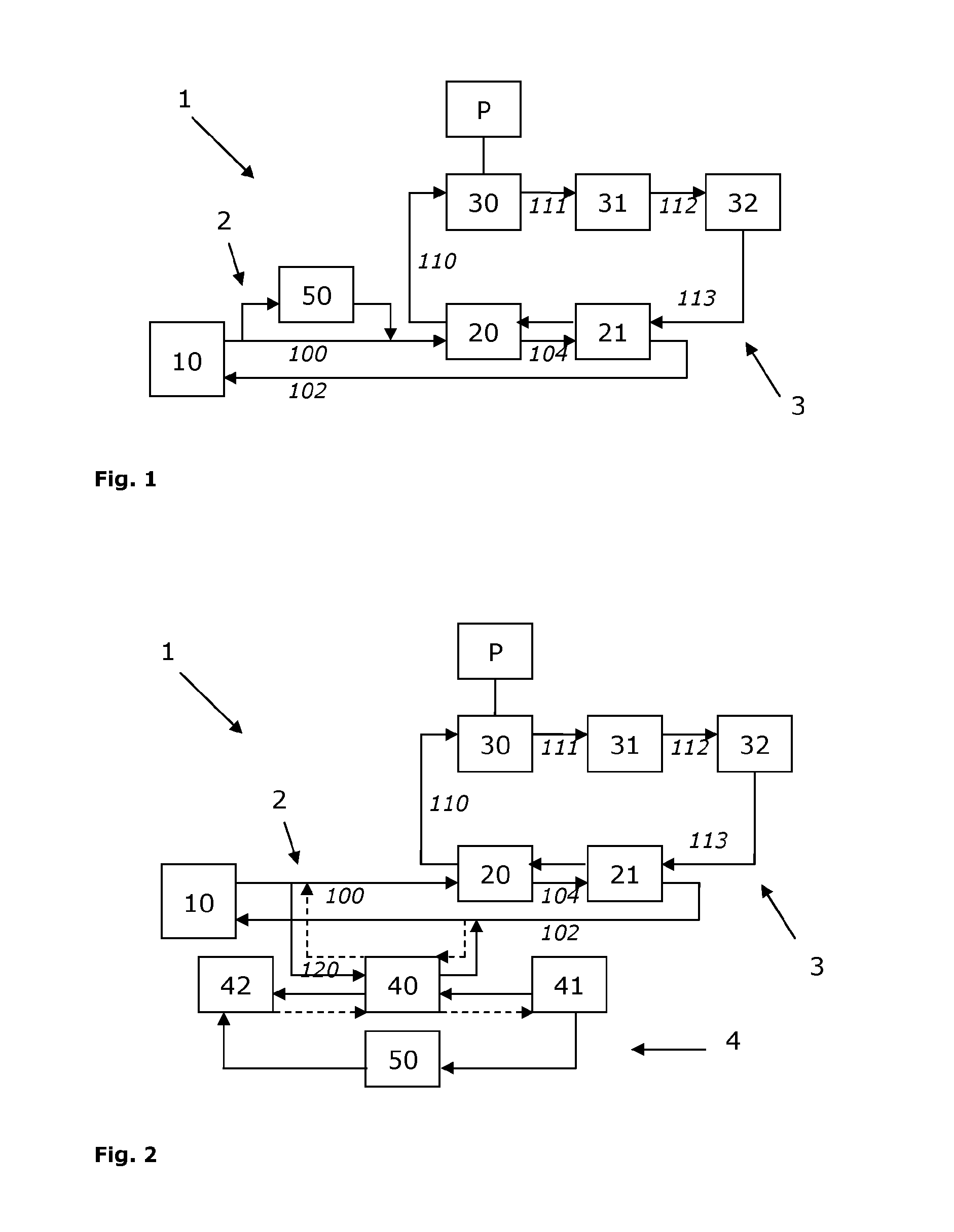
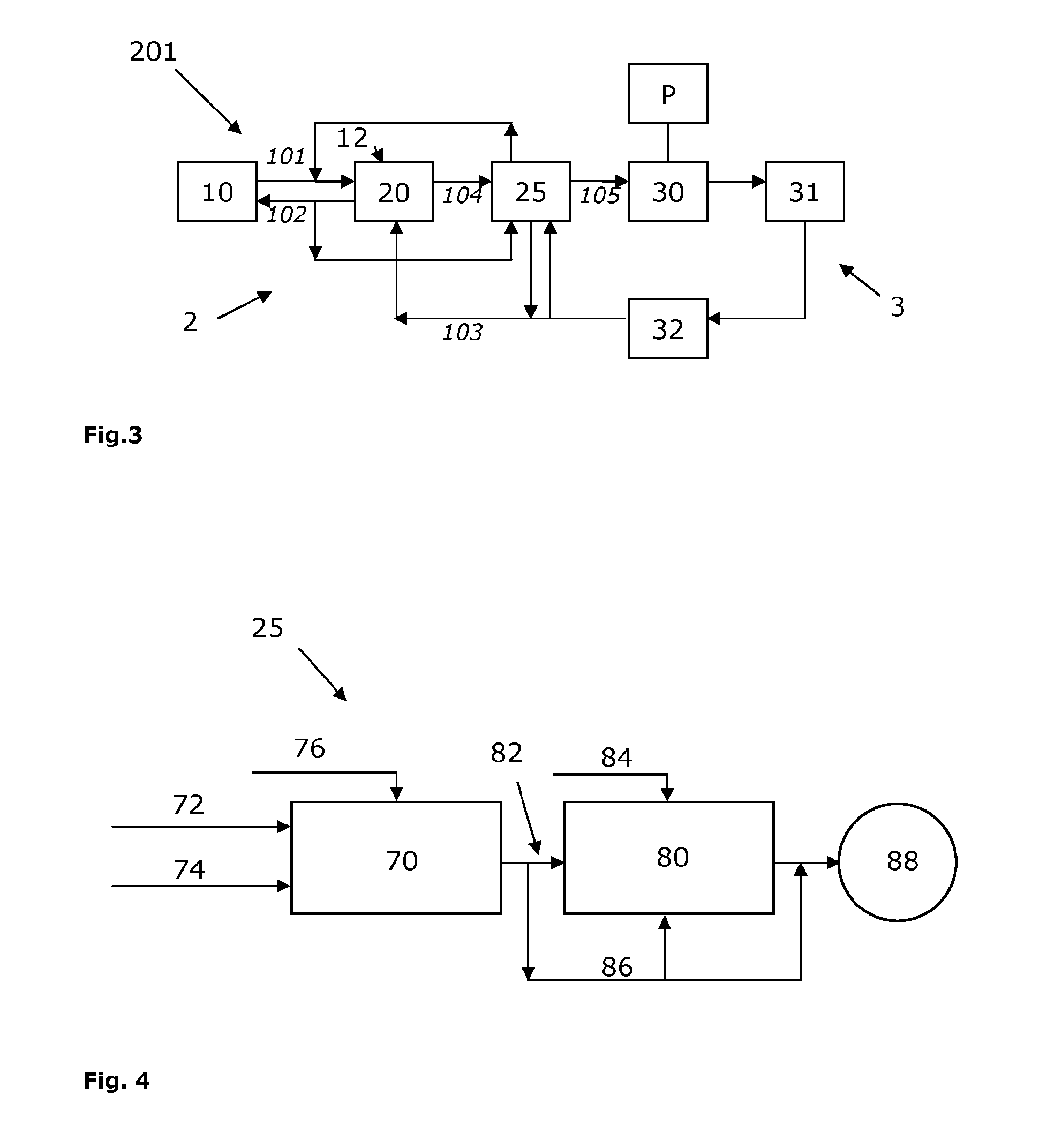
[0043]In FIG. 3, the solar thermal power plant 201 according to the invention is schematically shown. The reference numbers that are similar to reference numbers indicating features in the prior art solar thermal power plants 1 as shown in FIGS. 1 and 2, refer to similar features that operate in a similar way. The solar thermal power plant 201 according to the invention comprises a solar collection system 10 for heating the molten salts mixture in the heat transfer fluid circuit 2 to a temperature of approximately 550° C. by the concentrated solar radiation emitted onto the solar collection system 10. The molten salts mixture typically consists of a mixture of KNO3 and NaNO3. These salts can be used at operation temperatures up to 550° C. and these salts are non-toxic. Due to such a high operating temperature, using molten salts mixture as heat transfer fluid results in a more efficient steam cycle, for instance when compared to using oil as the heat transfer fluid.
[0044]In the heat...
third embodiment
[0064]In FIG. 7 the back-up boiler system 25 according to the invention is shown. This embodiment differs from the embodiment shown in FIG. 6 in that the convection section 80 is directly coupled to the combustion chamber 70. No flue gas supply 82 between the combustion chamber 70 and the convection section 80 is provided. Furthermore, the quench air inlet 84 is provided downstream of the valve means 81 to supply quench air to the inner space of the convection section downstream of the heat exchanger 90 for preheating boiler feed water. For explanation of the other features and operation of the back-up boiler system 25 as shown in FIG. 7, reference is made to the description relating to FIGS. 5 and 6.
fourth embodiment
[0065]In the back-up boiler system 25 as shown in FIG. 8, the differences with respect to the embodiment of FIG. 7 lie in the fact that a heat exchanger 94 for steam generation or superheating the steam is provided upstream of the heat exchanger 92 for preheating the molten salts mixture. Furthermore, a second valve means 83 is provided, to provide bypass possibilities to allow the flue gas to bypass the heat exchanger 92 for-preheating molten salts mixture. Also a second quench air inlet 87 is provided downstream of the second valve means 83 and upstream of the first valve means 81, to supply quench air to the convection section 80 inner space such that the air passing any heat exchanger, 90, 96, 98 downstream thereof has been quenched before passing any of said heat exchangers 90, 96, 98. After passing the heat exchanger 90 for preheating boiler feed water, the first quench air inlet 84 supplies quench air to the convection section 80 inner space such that the air contacting the h...
PUM
 Abstract
Description
Claims
Application Information
 - R&D
- Intellectual Property
- Life Sciences
- Materials
- Tech Scout
- Unparalleled Data Quality
- Higher Quality Content
- 60% Fewer Hallucinations
Browse by: Latest US Patents, China's latest patents, Technical Efficacy Thesaurus, Application Domain, Technology Topic, Popular Technical Reports.
© 2025 PatSnap. All rights reserved.Legal|Privacy policy|Modern Slavery Act Transparency Statement|Sitemap|About US| Contact US: help@patsnap.com


