
Gyroscopes based on nitrogen-vacancy centers in diamond

a gyroscope and diamond technology, applied in the field of gyroscopes, can solve the problems of relative phase shift of the magnetic sublevel, and achieve the effects of large geometric phase shift, small dimension, and thermal robustness

Active Publication Date: 2015-04-02
RGT UNIV OF CALIFORNIA
View PDF2 Cites 111 Cited by
  • Summary
  • Abstract
  • Description
  • Claims
  • Application Information

AI Technical Summary

Benefits of technology

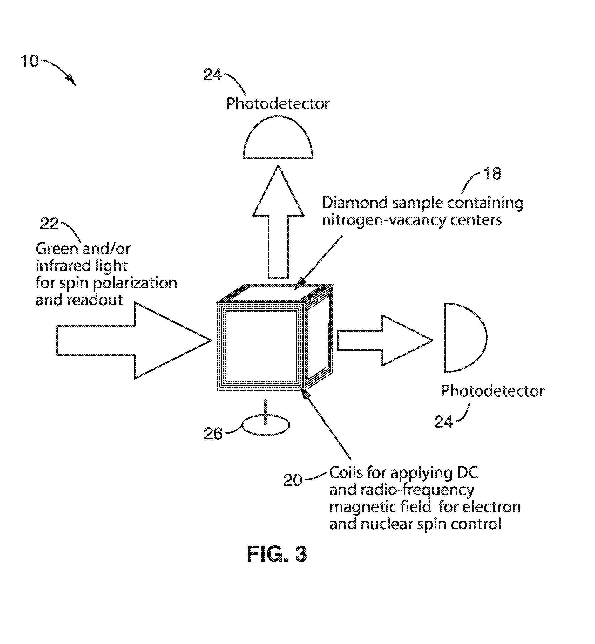
The present invention is about using nitrogen-vacancy centers in diamonds to create gyroscopic sensors. The main advantages of using this approach are the potential small size and thermal stability of the sensors, which can operate from cryogenic temperatures to 600-700 K. The geometric-phase effects in diamond can also be used to observe large phase shifts in single nitrogen-vacancy centers. The invention is a solid-state gyroscope based on ensembles of negatively charged nitrogen-vacancy centers. The sensitivity of the sensor can be achieved by measuring the rotation-induced phase shifts in the electronic ground-state coherences of the nitrogen-vacancy centers. The incorporation of dynamical decoupling to suppress dipolar relaxation can improve the sensitivity. Overall, this invention provides a novel and promising approach for creating high-quality array sensors for various applications.

Problems solved by technology

This results in relative phase shifts of the magnetic sublevels.

Method used


Image

  • Gyroscopes based on nitrogen-vacancy centers in diamond
  • Gyroscopes based on nitrogen-vacancy centers in diamond
  • Gyroscopes based on nitrogen-vacancy centers in diamond

Examples


example 1

[0092]In order to demonstrate the functionality of the methods, an apparatus 140 shown schematically in FIG. 8 was assembled. The apparatus 140 used a high pressure high temperature (HPHT) diamond slab 142. The diamond 142 had a nitrogen concentration of approximately 200 ppm and a concentration of NV− centers of 12 ppm. The diamond was cut perpendicular to the [100] crystallographic direction.

[0093]The diamond 142 is located in a static magnetic field produced by a permanent magnet 144. A microwave (MW) generator 158 sent current through a wire located on top of the diamond 142 that produced the MW field. Green (532 nm) light 146 from a laser 148 was focused onto the diamond 142 using a confocal setup with an aspheric lens 150 with a focal length of 4 mm and a numerical aperture NA=0.60.

[0094]The resulting red fluorescence from the diamond 142 was detected with a photodiode 154 after passing through a dichroic mirror 152 and a filter 156. The amount of red fluorescence as a functio...

example 2

[0097]To further demonstrate the methods, the transfer of the polarization of the electron spins of negatively charged nitrogen vacancy (NV) centers to the nuclear spins at the excited-state level anti-crossing (ESLAC) of the center was demonstrated. Polarization of 80% for the 14N nuclear spins within the NV centers, as well as a 50% polarization of proximal 13C nuclear spins was observed.

[0098]A type-Ib diamond with initial nitrogen concentration of 50 ppm was obtained and irradiated with 3 MeV electrons and annealed at 750° C. for 2 hours to provide a sensor platform. The NV-center concentration in the diamond after this process is estimated to be on the order of 10 ppm. The inhomogeneously broadened full width half maximum of the ground-state resonance is about 2.5 MHz, so the hyperfine splitting in the ground state (2.14 MHz) due to interaction with 14N was discernible.

[0099]Using a similar apparatus as that shown in FIG. 8, a spherical lens with focal length of 15 mm was provi...


PUM


Abstract

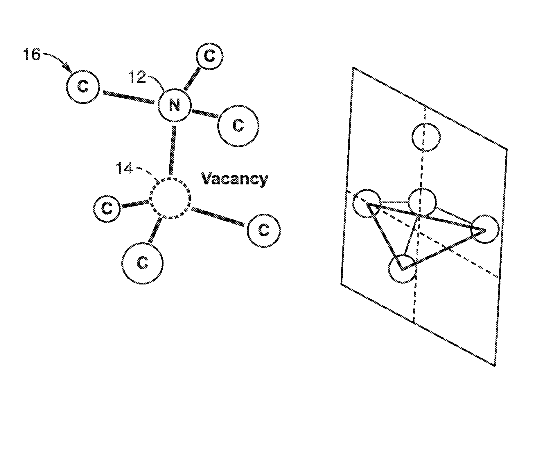
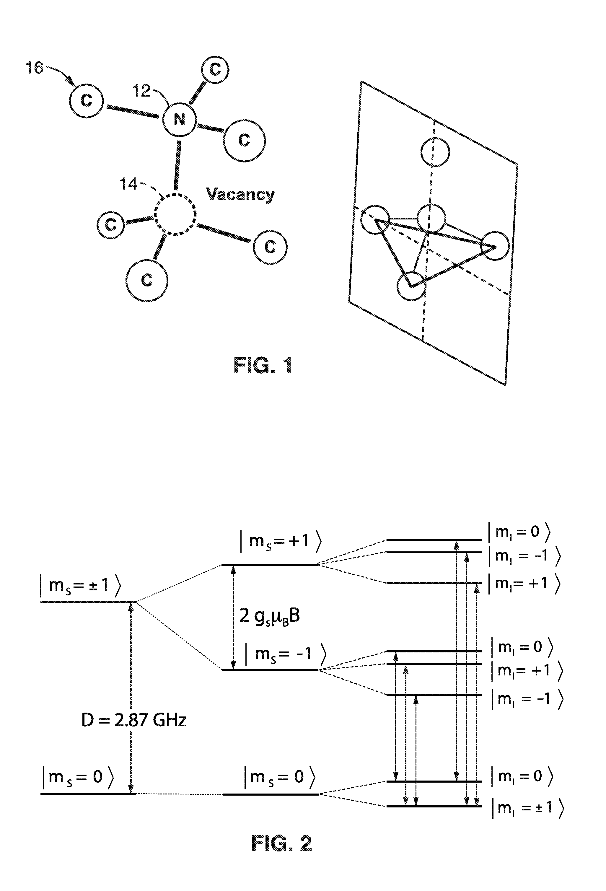
A solid-state gyroscope apparatus based on ensembles of negatively charged nitrogen-vacancy (NV−) centers in diamond and methods of detection are provided. In one method, rotation of the NV− symmetry axis will induce Berry phase shifts in the NV− electronic ground-state coherences proportional to the solid angle subtended by the symmetry axis. A second method uses a modified Ramsey scheme where Berry phase shifts in the 14N hyperfine sublevels are employed.

Description

CROSS-REFERENCE TO RELATED APPLICATIONS[0001]This application is a 35 U.S.C. §111(a) continuation of PCT international application number PCT / US2013 / 036435 filed on Apr. 12, 2013, incorporated herein by reference in its entirety, which claims priority to, and the benefit of, U.S. provisional patent application Ser. No. 61 / 624,249 filed on Apr. 13, 2012, incorporated herein by reference in its entirety. Priority is claimed to each of the foregoing applications.[0002]The above-referenced PCT international application was published as PCT International Publication No. WO 2014 / 011286 on Jan. 16, 2014 and republished on Mar. 20, 2014, which publications are incorporated herein by reference in their entireties.STATEMENT REGARDING FEDERALLY SPONSORED RESEARCH OR DEVELOPMENT[0003]This invention was made with Government support under FA9550-11-1-0270 awarded by the Air Force Office of Scientific Research (AFOSR), and 0855552 awarded by the National Science Foundation (NSF). The Government ha...

Claims


Application Information

Patent Timeline
IPC IPC(8): G01C19/62G01R33/46
CPCG01R33/46G01C19/62G01C19/58
Inventor BUDKER, DMITRYLEDBETTER, MICAHJENSEN, KASPERJARMOLA, ANDREY
Owner RGT UNIV OF CALIFORNIA
Learn More