Power transmission system

a transmission system and power technology, applied in the direction of fluid couplings, rotary clutches, gearing, etc., can solve the problem of not being able to achieve the desired vibration damping performance of the damper device, and achieve the effect of improving the vibration damping performance of the pendulum damper and increasing the inertia moment of the rolling member

US20150090555A1Inactive Publication Date: 2015-04-02TOYOTA JIDOSHA KK
2 Cites 6 Cited by

Patent Information

Authority / Receiving Office
US · United States
Patent Type
Applications(United States)
Current Assignee / Owner
Publication Date
2015-04-02
Estimated Expiration
Not applicable · inactive patent

Smart Images

  • Figure 1
    Figure 1
  • Figure 2
    Figure 2
  • Figure 3
    Figure 3
Patent Text Reader

Abstract

A power transmission system having a pendulum damper is provided. A rolling member of the pendulum damper is arrange in a rotary member, and a vibration damping performance of the pendulum damper is enhanced by increasing an inertia moment of the rolling member to be larger than that of the rotary member. The power transmission system is comprised of a hydraulic route for transmitting power between an input member and an output member through a fluid coupling, a mechanical route for transmitting power between the input member and the output member by engaging a lockup clutch, a pendulum damper that damps torsional vibrations of the output member by an oscillating motion caused by the torsional vibrations, and an elastic damper that damps the torsional vibrations by a relative rotation between a drive member and a driven member connected through an elastic member. The pendulum damper is disposed on the mechanical route, and one of the lockup clutch and the elastic damper is disposed on an output side of the pendulum damper.
Need to check novelty before this filing date? Find Prior Art

Description

TECHNICAL FIELD

[0001] The present invention relates generally to a system for transmitting power, and more particularly, to a power transmission system having a fluid coupling and a damper for damping torsional vibrations of a rotary member by a reciprocating motion of a rotary member arranged around the rotary member.BACKGROUND ART

[0002] Torsional vibrations on a rotary member such as a drive shaft for transmitting torque of a prime mover are caused by torque pulses resulting from driving the prime mover connected to the rotary member. One example of a damper for damping such torsional vibrations on the rotary member is described in Japanese Patent Laid-Open No. 2011-504986.

[0003] According to the teachings of Japanese Patent Laid-Open No. 2011-504986, a damper device as a centrifugal pendulum device comprised of a speed adaptive absorber and two dampers is arranged in a torque converter having a lockup clutch. The damper device is further comprised of a support device connected to a ...

Examples

Embodiment Construction

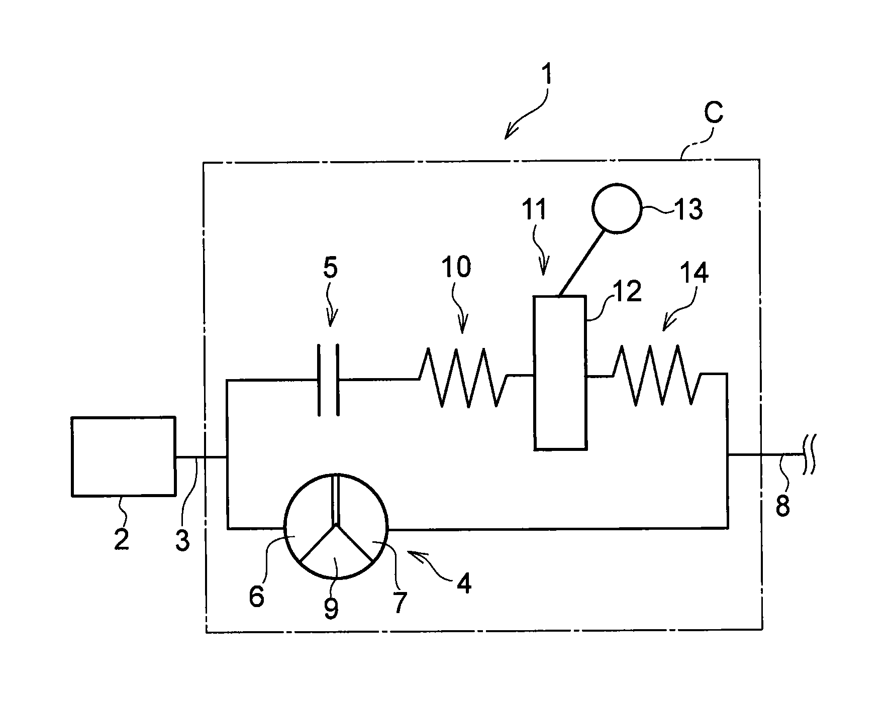
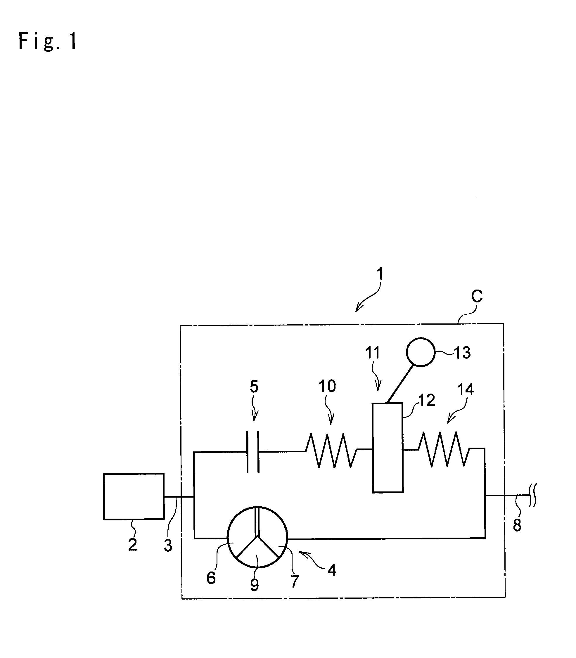
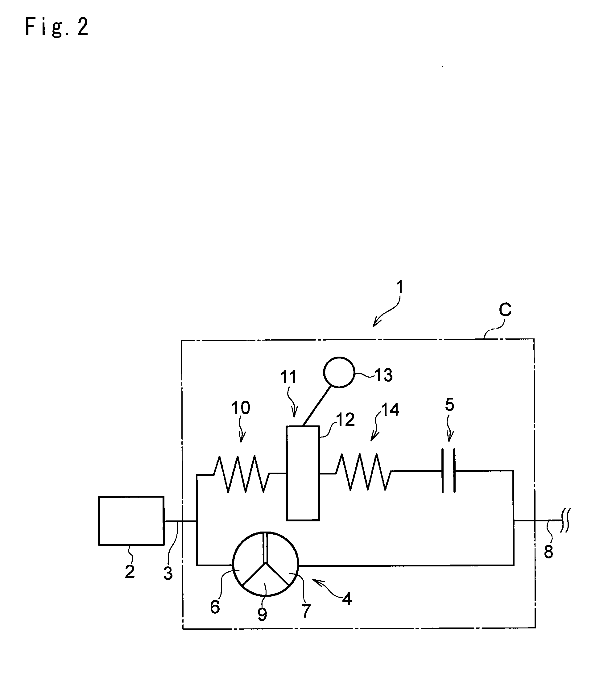
[0019]Next, preferred examples of the present invention will be explained hereinafter. Referring now to FIG. 1, there is shown the first example of the power transmission system of the present invention. As shown in FIG. 1, a torque converter 4 as a torque multiplier is connected to an output shaft 3 of a prime mover 2. For example, an internal combustion engine such as a gasoline engine, an electric motor, and a hybrid drive unit comprised of the engine and the motor may be used as the prime mover 2. In the following explanation, the prime mover 2 will simply be called the “engine”2.

[0020]The torque converter 4 is provided with an after-mentioned lockup clutch 5. A pump impeller 6 serves as an input member of the torque converter 4, and although not shown in the drawings, a plurality of pump blades are attached to an inner face of the pump impeller 6. A pump shell is integrated with a front cover (both not shown) to form a liquid-tight casing C, and the front cover is connected to ...