Single-stage ac-dc power converter with flyback pfc and improved thd

a flyback technology, applied in the field of high-efficiency single-stage ac-dc power converters, can solve the problems of large output current ripple, low power factor or ratio of real power to apparent power, converter draws excess current but fails to use excess current to perform or accomplish any circuit function, etc., to achieve the effect of improving thd results and reducing curren

Active Publication Date: 2015-04-02
GE LIGHTING SOLUTIONS LLC
View PDF6 Cites 9 Cited by
  • Summary
  • Abstract
  • Description
  • Claims
  • Application Information

AI Technical Summary

Benefits of technology

[0022]As an example of one of the above embodiments of the invention, the passive voltage multiplier circuit is preferably configured a Zener resistor multiplier arrangement that can be made to approximate any polynomial function, not just a squaring function, such as Xn where “n” can be any real number. This arrangement can be added to existing designs of PFC converters (other than just buck PFC converters), such as flyback PFC converters, and can improve the THD results associated with such PFC converters, which reduces the current that must be drawn from the AC power supply. This multiplier circuit is typically configured to be connected to the input voltage sensing pin of the control chip of the PFC converter.
[0023]Yet further, it will be appreciated by those of skill in the art that the improvements described herein can be used to advantage not only in two-stage LED drivers or other types of power supplies but also in single-stage LED driver and other power supply designs, as will be apparent based on the teachings contained herein.

Problems solved by technology

A drawback with this configuration is that the power factor or ratio of real power to apparent power is usually very low.
Thus, the converter draws excess current but fails to use the excess current to perform or accomplish any circuit functions.
However, this type of two-stage architecture uses many components and processes the power twice.
But, a major drawback with the single-stage architecture is that it has a large output current ripple, which is at twice the AC line frequency.
The magnitude of this ripple can overdrive conventional feedback networks—forcing them outside of their linear response region or degrading their ability to maintain a high power factor.
However, although a filtering capacitor having a large capacitance value smoothes out the large output current ripple delivered to the load without interfering with the control loop, such a filtering capacitor is usually an electrolytic capacitor that tends to be large and expensive and tends to degrade circuit reliability.
In addition, the large capacitance of such a filtering capacitor slows the response time of the control loop—resulting in excessive current, which can overdrive, and potentially damage, the load.
The excessive currents typically occur when the load is connected to a pre-powered converter (e.g., “hot plug”, “hot insertion”).
The output capacitor at this point is fully charge to the maximal output voltage; thus, the energy stored in it can damage the load right at the connection of it to the converter.
Such costs, however, must also be weighed against the necessary performance criteria of LED drivers, which must not only be efficient but also generate minimal ripples in the output current provided to the LED load.
Large current ripples reduce the reliability, longevity, and luminance output of the LEDs, which is obviously not desirable.
A drawback of such conventional designs, however, is the fact that these two stages require two independently controlled power switches and two control circuits (or “controllers”).
The two-stage design suffers from an increased component count and a higher-than-desired cost.
Although it would be cheaper to employ a passive PFC as the first stage, such topology architectures usually cannot provide the necessary efficiency required by energy regulations or minimal current ripples required by the LED load.
Another drawback to such two stage LED driver designs is that each LED driver is typically configured for one specific output current level.
However, such low cost ICs generally do not work well with buck topologies because they do not provide good THD results (i.e., they often draw more than desired—or required by law or regulation—power from the AC power supply).

Method used


Image

  • Single-stage ac-dc power converter with flyback pfc and improved thd
  • Single-stage ac-dc power converter with flyback pfc and improved thd
  • Single-stage ac-dc power converter with flyback pfc and improved thd

Examples


Embodiment Construction

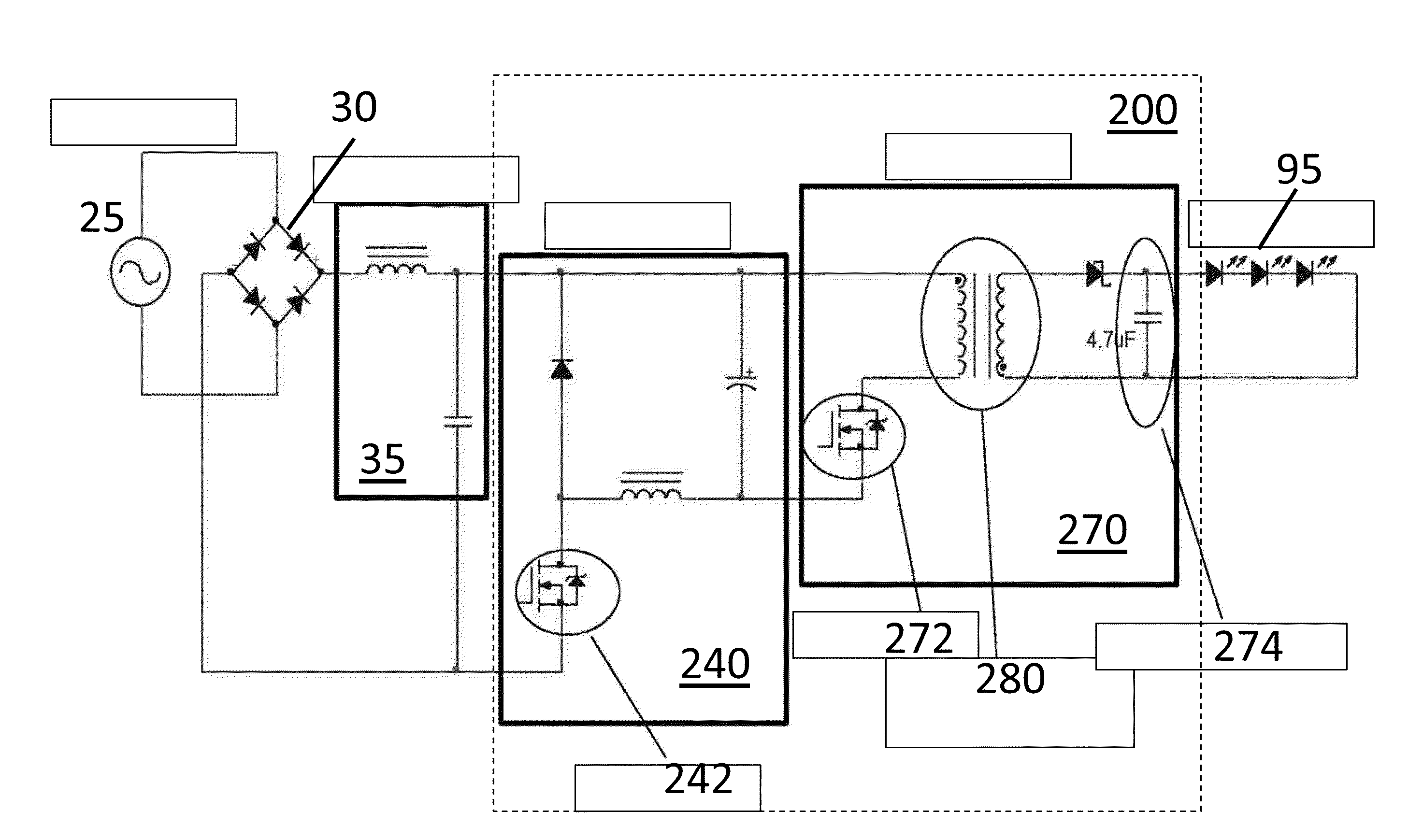
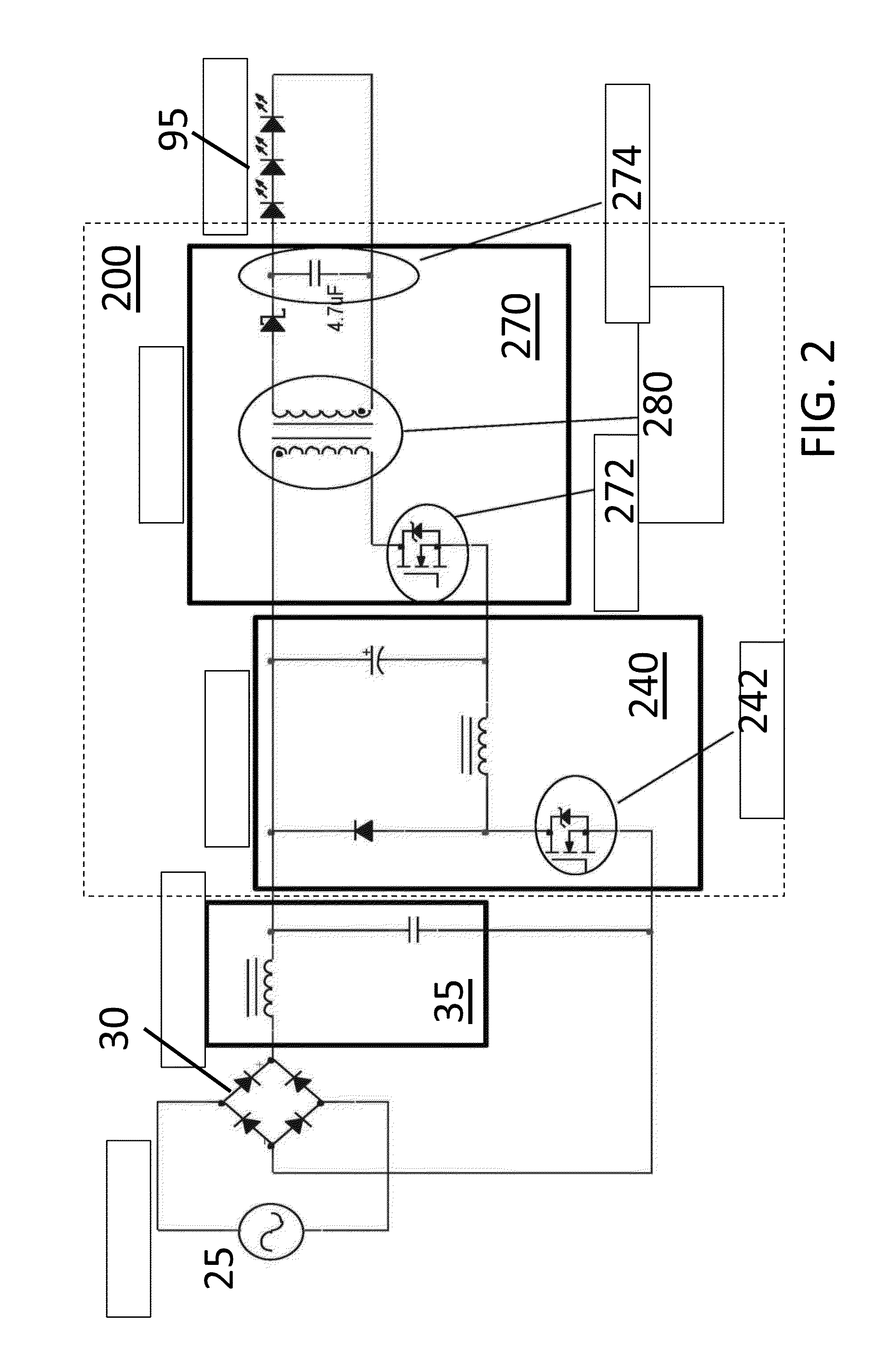
[0018]Given the aforementioned deficiencies, a need exists for systems, methods, and devices providing a low cost and efficient LED driver. Particularly, what are needed are systems, methods, and devices that enable an active buck topology, functioning in transition mode, to be used as a first PFC stage of an LED driver whereby the buck topology is designed in such a manner that it can be controlled with a low cost control chip that is typically only used with boost or flyback topologies, while still achieving good THD results. Further, what are needed are systems, methods, and devices that enable a flyback current circuit to be used as a second stage of an LED driver, whereby the flyback circuit includes a switch or jumper setting selectable by the user that enables the LED driver to be toggled or switched between two different output currents—depending upon the requirements of the LED load being powered by the LED driver.

[0019]Embodiments of the present invention provide a light e...


PUM


Abstract

A single-stage AC-DC power converter for powering a load at a substantially constant current, and related methods and systems. The AC-DC power converter includes a high power factor correction (PFC) circuit configured in a flyback topology and operating in transition mode. The flyback PFC circuit has a PFC controller and is configured to draw an input AC current from an AC power supply. The input AC current has a first total harmonic distortion (THD). The flyback PFC circuit outputs a DC current to the load. The PFC controller is configured to sense a rectified input voltage. By multiplying the rectified input voltage sensed by the PFC controller, the input AC current drawn by the flyback PFC circuit has a second, much improved THD, which is achievable without the need of an expensive PFC controller. The rectified input voltage sensed by the PFC controller is multiplied using a Zener diode ladder.

Description

I. FIELD OF THE INVENTION[0001]The present invention relates generally to power supplies and, more particularly, to a high-efficiency, single-stage AC-DC power converter having a flyback power factor correction (PFC) circuit, running in transition mode, that achieves an improved total harmonic distortion (THD) result by multiplying the input voltage sensed by the PFC controller.II. BACKGROUND OF THE INVENTION[0002]Power converters are used in a variety of portable electronic devices, including laptops, mobile devices, cellular phones, electronic digital pads, video cameras, digitals cameras, and the like. In addition, power converters may be used in non-portable applications, such as liquid-crystal display (LCD) backlighting, automotive lighting, and other general purpose or specialty lighting.[0003]Power converters come in many forms. Some converters are DC-DC converters, which convert a Direct Current (DC) input voltage to a different DC output voltage. AC-AC converters convert on...

Claims


Application Information

Patent Timeline
Patent Type & Authority Applications(United States)
IPC IPC(8): H02M3/335H05B33/08H05B44/00
CPCH05B33/0806H02M3/33507H02M1/12H02M1/4225Y02B70/10H05B45/355H05B45/385H05B45/345H05B45/375H02M1/0025H02M1/007
Inventor LEVY, YEHUDA DANIEL
Owner GE LIGHTING SOLUTIONS LLC
Why Eureka
Try Eureka