Cold cathode ionization vacuum gauge

Active Publication Date: 2015-04-02
MKS INSTR INC
View PDF2 Cites 10 Cited by
  • Summary
  • Abstract
  • Description
  • Claims
  • Application Information

AI Technical Summary

Benefits of technology

This invention has several benefits. It uses separate measurements of discharge current and leakage current to ensure long-term stability. The starter device helps to achieve reproducible and rapid startup. Additionally, it prevents measurement errors during operation of the cold cathode ionization vacuum gauge.

Problems solved by technology

The lack of a hot filament, on the other hand, complicates gauge monitoring as there is no independent electron current to be measured and controlled, unlike in a HCIVG where the electron emission current is monitored and used to assure the validity of the ion current measurements.
In other words, as the CCIVG starts to lose sensitivity, both the electron and ion currents decrease over time; however, since the user does not have direct access to electron current (in contrast to a hot cathode gauge), there is no way to know whether a drop in ion current is due to a reduction in electron current in the discharge or a reduction in process pressure.

Method used


Image

  • Cold cathode ionization vacuum gauge
  • Cold cathode ionization vacuum gauge
  • Cold cathode ionization vacuum gauge

Examples


Embodiment Construction

[0044]A description of example embodiments of the invention follows.

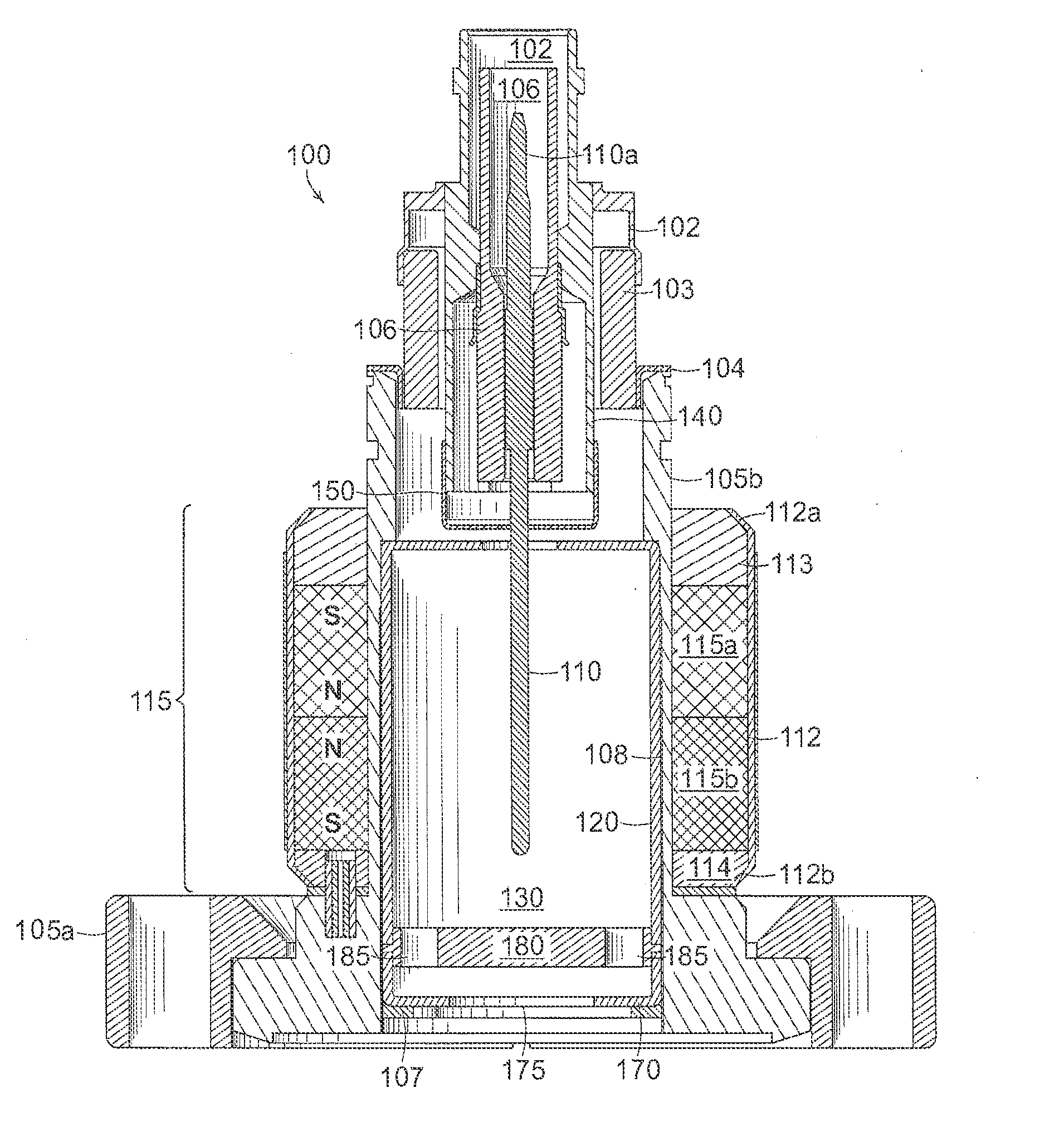
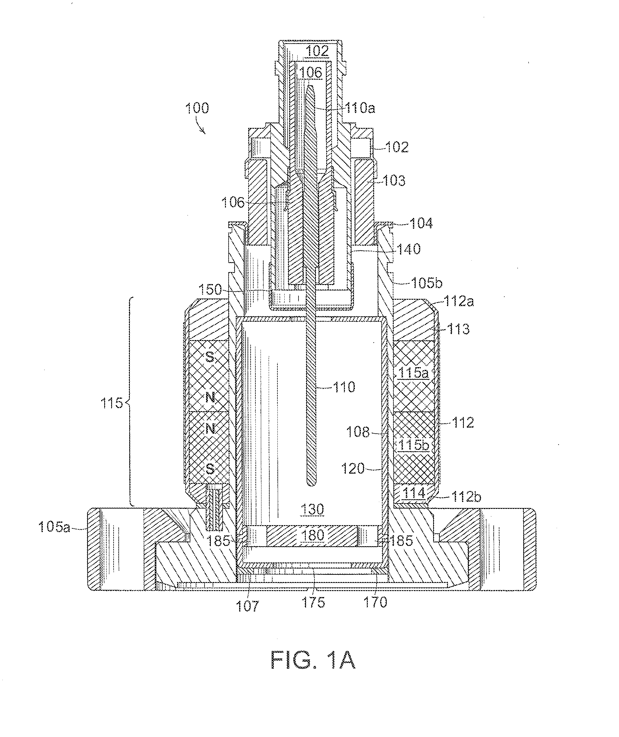
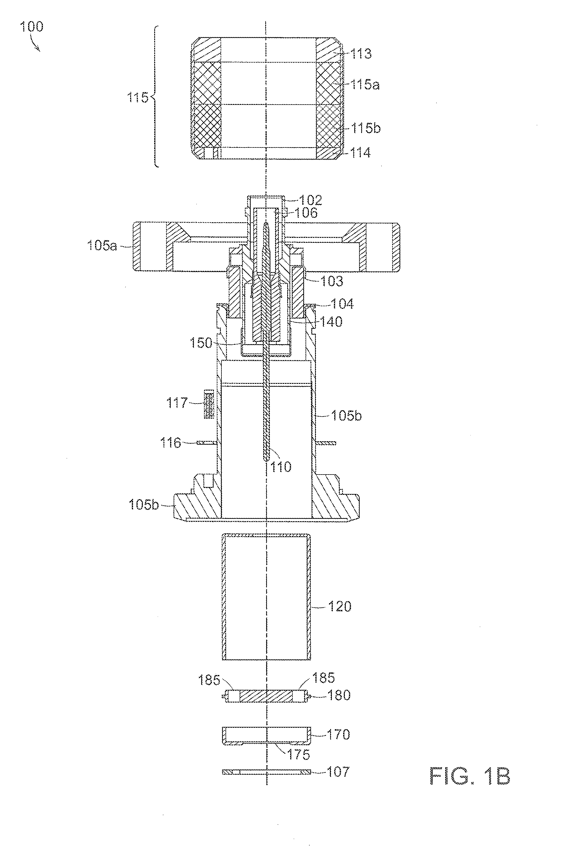
[0045]The cold cathode ionization vacuum gauge described herein relies on the inverted magnetron principle. The gauge is of cylindrical symmetry. A large voltage potential difference (i.e., radial electric field) between the anode pin (located at the axis) and the cathode cylindrical envelope provides energy to the electrons for the ionization events to occur. A crossed axial magnetic field provides the electron trajectory path length required to maintain a discharge inside the envelope. The discharge current is the measured quantity that is proportional to the pressure in the system.

[0046]The discharge is established through an avalanche ionization process that generally starts with a single electron being released into the ionization volume of the gauge. The process responsible for releasing an electron can include a field emission event or a cosmic ray ionization process. The avalanche process relies on the long ...


PUM

PropertyMeasurementUnit
Pressureaaaaaaaaaa
Currentaaaaaaaaaa
Lengthaaaaaaaaaa

Abstract

A cold cathode ionization vacuum gauge includes an extended anode electrode and a cathode electrode surrounding the anode electrode along its length and forming a discharge space between the anode electrode and the cathode electrode. The vacuum gauge further includes an electrically conductive guard ring electrode interposed between the cathode electrode and the anode electrode about a base of the anode electrode to collect leakage electrical current, and a discharge starter device disposed over and electrically connected with the guard ring electrode, the starter device having a plurality of tips directed toward the anode and forming a gap between the tips and the anode.

Description

RELATED APPLICATIONS[0001]This application is a divisional application of U.S. application Ser. No. 14 / 500,820, filed on Sep. 29, 2014, which corresponds to International Application No. PCT / US2014 / 058088, filed on Sep. 29, 2014, which claims the benefit of U.S. Provisional Application No. 61 / 884,797, filed on Sep. 30, 2013. The entire teachings of the above applications are incorporated herein by reference.BACKGROUND OF THE INVENTION[0002]Cold cathode ionization vacuum gauges are well known. Three commonly known cold cathode ionization vacuum gauges include normal (noninverted) magnetron type gauges, inverted magnetron type gauges, and Philips (or Penning) gauges. All of these types of gauges have a pair of electrodes (i.e., an anode and a cathode) in an evacuated non-magnetic envelope which is connected to the vacuum to be measured. A high DC voltage potential difference is applied between the anode electrode and the cathode electrode to cause a discharge current to flow therebetw...

Claims


Application Information

Patent Timeline
IPC IPC(8): G01L21/34H01J41/06
CPCH01J41/06G01L21/34Y10T29/49007H01J9/50Y02W30/82G01L19/06
Inventor BRUCKER, GERARDO A.SWINNEY, TIMOTHY C.KELLY, BRANDON J.FUNARI, ALFRED A.SCHOTT, MICHAEL N.SCHARTAU, KRISTIAN S.
Owner MKS INSTR INC
Why Eureka
Try Eureka