Tunable AIG for Improved SCR Performance

Inactive Publication Date: 2015-04-02
PEERLESS MFG CO
View PDF7 Cites 10 Cited by
  • Summary
  • Abstract
  • Description
  • Claims
  • Application Information

AI Technical Summary

Benefits of technology

[0012]It is an objective of the present invention to provide a system and method for individual control of reagent at different i

Problems solved by technology

However, on large ducts, or for exhaust gas flows with high velocities, or for low temperature applications, the distribution and decomposition of urea based reagent poses challenges when injected from the exhaust duct wall.
While the application cites a plurality of decomposition ducts each with an injector, it is does not disclose the individual control of reagent at different injection rates in each of the decomposition ducts, nor does it disclose the potential need to inject higher volumes of reagent beyond 10 gph.
This has the disadvantage of chang

Method used


Image

  • Tunable AIG for Improved SCR Performance
  • Tunable AIG for Improved SCR Performance
  • Tunable AIG for Improved SCR Performance

Examples


Embodiment Construction

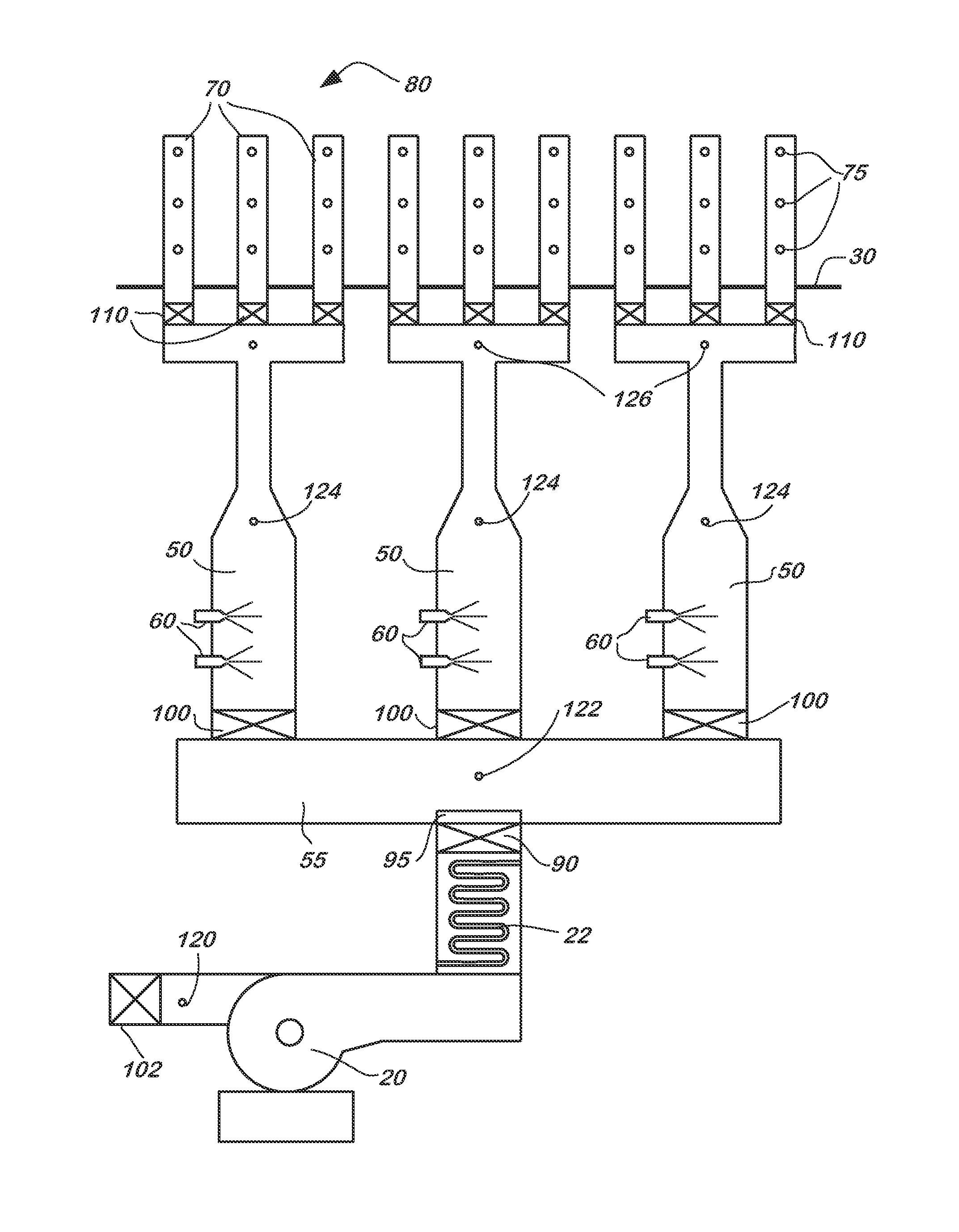
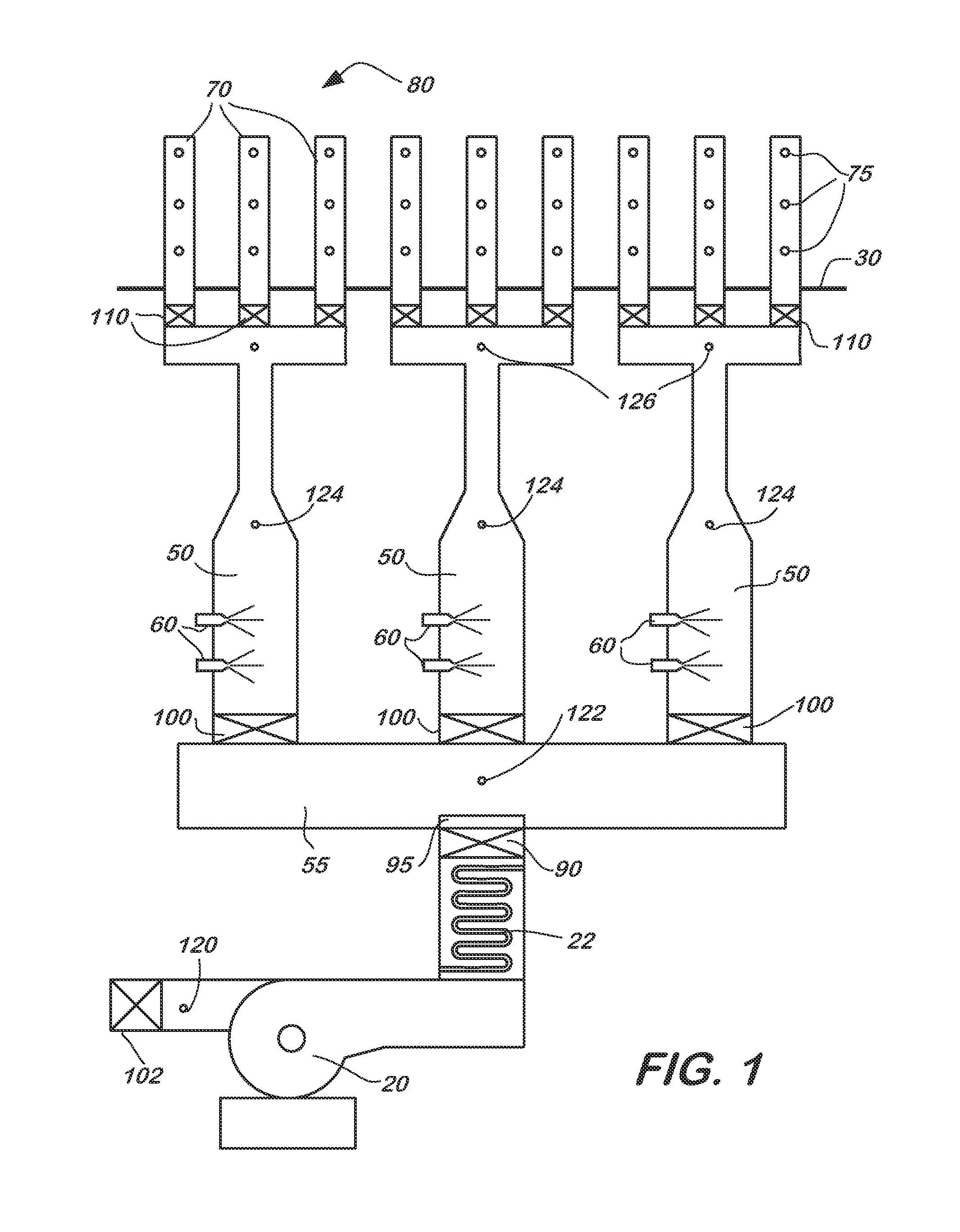
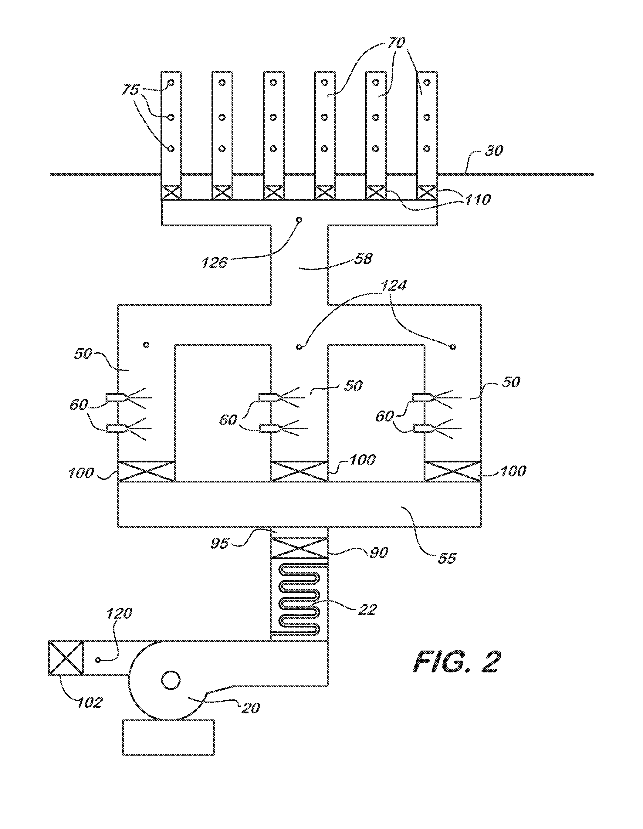
[0045]In one exemplary embodiment illustrated in FIG. 1, the current invention provides a plurality of continuous urea decomposition ducts (50) connected to individual AIG injection lances (70), or AIG sections of multiple injection lances. On each decomposition duct (50), a single or multiple aqueous reagent injectors or atomizers (60) with metering valves are mounted to allow control of the reagent injection rate separately from that of the hot carrier gas flow. In some advantageous embodiments, one or more metering valves and an atomizer are formed as an integral unit that defines an atomizing injector. A return flow injector, as described in U.S. Pat. No. 7,467,749, the specification of which is incorporated herein in its entirety, is particularly suitable for this application. In additional advantageous embodiments, an air assisted injection lance with a metering valve may be used, such as described in pending U.S. patent application Ser. No. 13 / 313,683, the specification of wh...


PUM

PropertyMeasurementUnit
Sizeaaaaaaaaaa
Sizeaaaaaaaaaa
Volumetric flow rateaaaaaaaaaa

Abstract

A system for controlling reagent flow to an exhaust of a lean burn combustion source includes a plurality of decomposition ducts each being connected to at least one injection lance of a reagent injection grid and supplying reagent and hot carrier gas to the injection lance, and at least one metering valve in communication with each of the plurality of decomposition ducts that controls reagent injection rate to the injection lance. A method of controlling a reagent flow to an exhaust of a lean burn combustion source includes providing a reagent injection grid having at least one injection lance, supplying the reagent and hot carrier gas to the reagent injection grid from a plurality of decomposition ducts coupled to the injection grid, and controlling reagent injection rate to the injection grid via at least one metering valve in communication with each of the plurality of decomposition ducts.

Description

FIELD OF THE INVENTION[0001]The present invention relates generally to the reduction of oxides of nitrogen (NOx) emissions produced by lean burn combustion sources. In particular, the present invention provides a system and method for controlling the reagent flow to the exhaust of a lean burn combustor equipped with a NOx reduction catalyst and reagent injection grid, wherein the reagent injection rate to individual lances or groups of lances of the reagent injection grid is controlled by one or more metering valves affixed to the duct supplying hot carrier gas to the reagent injection grid.BACKGROUND OF THE INVENTION[0002]Selective Catalytic Reduction (“SCR”) processes have been widely applied to boilers and gas turbines for the reduction of nitrogen oxide emissions. Traditional reagents used in the process include anhydrous ammonia and aqueous based solutions of ammonia or urea. The use of aqueous based solutions generally requires that the ammonia or urea be vaporized to a gas fo...

Claims


Application Information

Patent Timeline
IPC IPC(8): B01D53/90
CPCB01D2251/2062B01D53/90F01N3/208F01N2610/02F01N2610/10F01N2610/105F01N2610/1453Y02T10/12
Inventor BRODERICK, JEFFREY MICHAELLINDEMANN, SCOTT H.BRODERICK, R. GIFFORDSCHINDLER, EDMUND S.VALENTINE, JAMES M.
Owner PEERLESS MFG CO
Why Eureka
Try Eureka