Atraumatic Medical Device

a medical device and traumatic technology, applied in the field of medical devices, can solve the problems of poor outcomes, significant morbidity and mortality, and little to no user feedback regarding the amount of applied force at the tip, and achieve the effects of facilitating catheter placement within the target site, reducing dislocation, and increasing contact surface area

Active Publication Date: 2015-04-16
MEDWERKS
View PDF4 Cites 65 Cited by
  • Summary
  • Abstract
  • Description
  • Claims
  • Application Information

AI Technical Summary

Benefits of technology

[0034]In another embodiment, the atraumatic tip can be combined with an inflatable balloon to help with flow directed placement or inject materials into the balloon to increase surface area of contact with the tissue or allow for injection of materials with magnetic properties which, when combined with an external magnetic field would allow catheter placement or securing to a site while minimizing dislodgement.
[0035]The catheter shaft could allow the insertion of additional catheters if needed and may have an injectable lumen to deliver fluids or drugs. This catheter shaft can have an open inner lumen that is configured to be compatible with a guidewire such that placement of the catheter within the target site is facilitated by advancement over a cardiac guidewire.
[0036]Alternately, in order to facilitate device insertion into the vasculature through a vascular introducer, the spring tip can be manufactured in such a way that the distal tip can be elongated by actuation. Elongation of the distal tip is enabled by advancing an inner member attached to the distal end of the spring tip material relative to the outer catheter that is attached to the proximal end of the spring tip material. This would protect the tip as the device passes through a hemostatic seal in the vascular introducer and through the vessels or chambers of the body, yet allow for actuation of the device into the desired configuration prior to engaging the distal tip with tissue at the target site.
[0037]In another embodiment, the mechanism for reducing the risk of trauma associated from the use of the device is to add a spring or shock-absorbing member behind the catheter tip itself or in the body of the catheter. This mechanism allows a catheter tip to function in its typical manner while providing a means of displacement absorption in the catheter without the application of significant additional force against a target site within the vasculature or cardiac structure. Additionally, this mechanism can be configured as a series of spring members within the catheter shaft, with sequential spring members being engaged as the forces applied to the catheter tip increased.

Problems solved by technology

Some of these devices cause trauma to the adjacent tissue with which they make contact due to the force with which they are advanced or placed, causing complications and poor outcomes.
Perforation of organs by these catheters and probes causes significant morbidity and mortality.
In addition, there are cases in which the catheter tips are intentionally applied against tissue, but there is little to no user feedback regarding the amount of applied force at the tip or the proximity of the tip to the tissue with which it is in contact.
Additionally, the tips are non-conductive and so are not useful for applications such as cardiac rhythm management or tissue signal recordings.
In certain medical conditions, the conduction system of the heart is abnormal, leading to slow or abnormal heart rhythm.
One problem with these pacemaker catheters or leads is that they can perforate the heart tissue.
Contraction of the heart muscle against the catheter or lead may cause the catheter or lead to erode through or perforate the muscle wall.
Perforation leads to leakage of blood from the heart to the pericardial sac that surrounds the heart.
This condition is called cardiac tamponade, which untreated often leads to death.
Motion or simple continued force may cause erosion or burrowing of the catheter or lead.
These procedures result in complications such as the aforementioned cardiac perforation in up to 2% of the procedures.
These have their own limitations related to suboptimal stability and potential migration.
Migration of a pacer lead, or loss of capture, results in an immediate inability to pace the heart muscle which can be deadly in a patient that requires pacing to ensure adequate rhythm.
Additional difficulties in positioning the catheter include placing it at the exact place needed or preventing its migration due to the poor ability to secure them at the area of need.
However, these existing methods have various limitations including the risk of poor contact at the required site, risk of trauma leading to organ perforation, migration away from area of implant or being flimsy or difficult to maneuver.
These contrast injections can add to patient risk by increasing the demand on the kidneys of the patient, particularly in patients that are already at risk of kidney failure.
Similarly, therapeutic catheters used to delivery energy (such as radiofrequency energy to alter cardiac tissue), alter cardiac temperature (such as cryoablation catheters), or image cardiac tissue (such as ultrasound catheters) require precise placement and inappropriate use can perforate the heart muscle.
During this tissue extraction, excessive force on the catheter during advancement or actuation can also result in perforation.
Additionally, there are systems that are used to deliver contrast or therapeutic agents to the vasculature, the heart or another target site in the body that do not have a mechanism to stabilize the system or protect the tissue from damage.
In certain locations, the left atrial wall can be as thin as 0.5 mm between the pectinate muscles which would make it susceptible to perforation or damage during a high-velocity contrast injection if the catheter orifice is too close to the atrial wall when the injection is performed.
It may also prevent a proximally directed force from applying a tensile force to the site and risk dislodging the electrode from the tissue.
If the tip of the catheter is too close to a fragile location in the left atrium, there is risk that the injection could damage or perforate the left atrial wall.

Method used


Image

  • Atraumatic Medical Device
  • Atraumatic Medical Device
  • Atraumatic Medical Device

Examples


Embodiment Construction

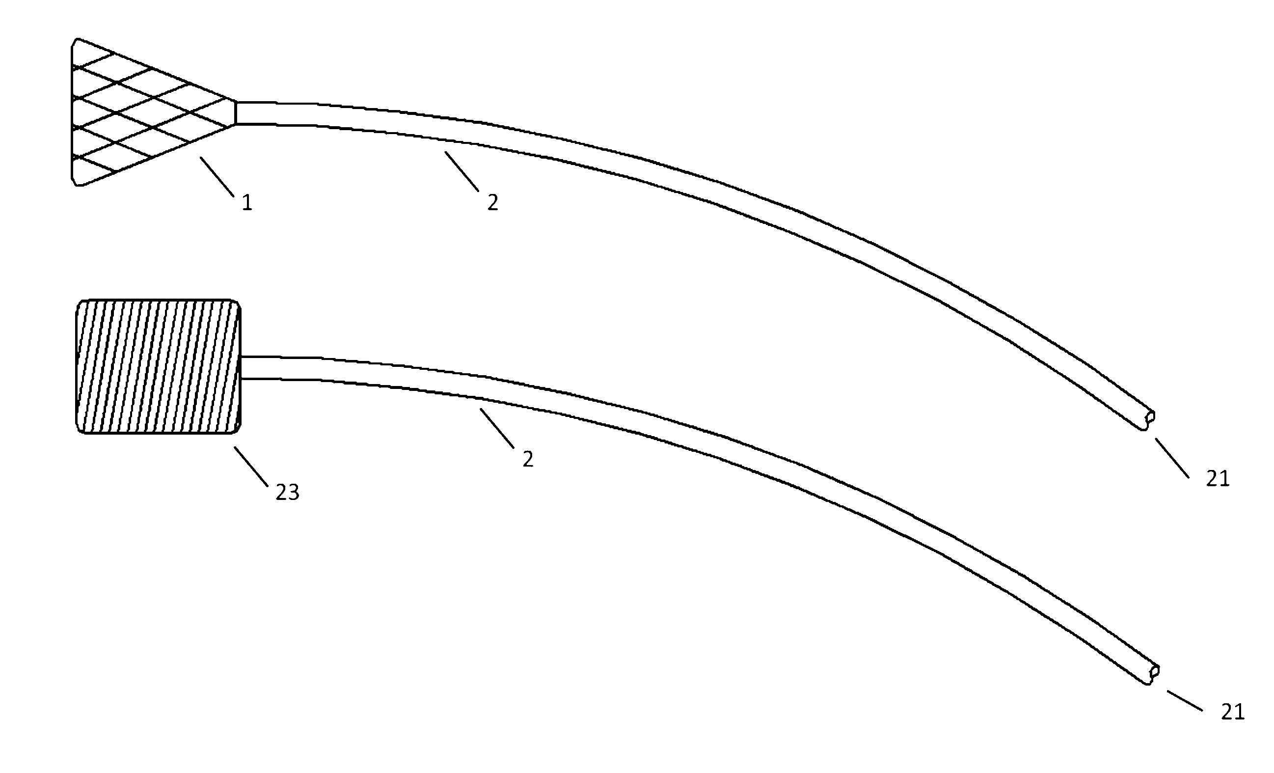
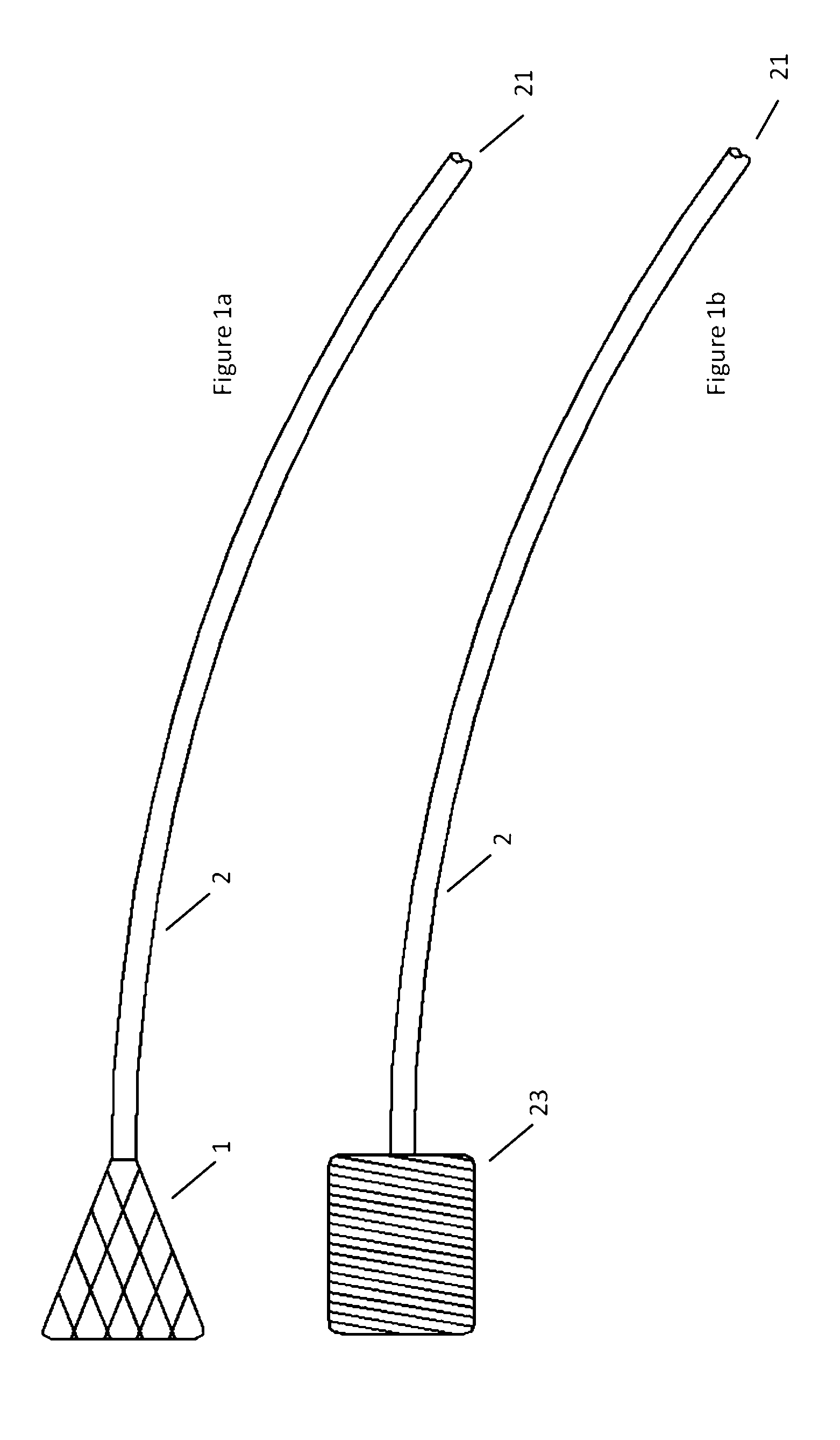
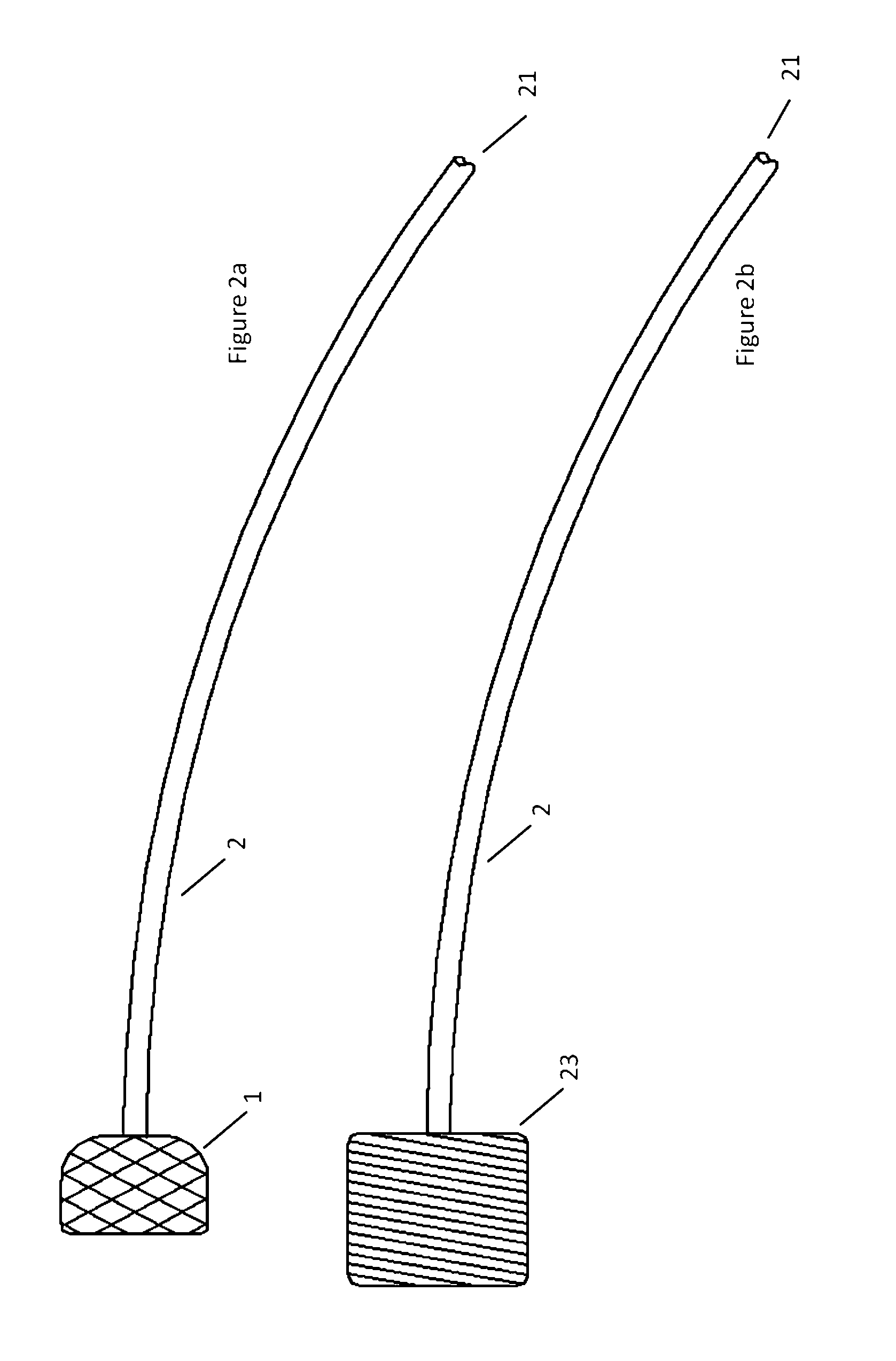
[0076]Turning now to the Figures, and first to FIG. 1, there is shown an embodiment of an atraumatic medical device of the invention. The device generally includes a catheter 2 and a spring tip 1 attached to the distal end of the catheter 2. In a relaxed state without contact against tissues or other structures within the body, the mesh spring tip 1 expands upon deployment through a catheter and takes a conical shape. In this embodiment, the tip is demonstrated as a mesh or braid, but can be manufactured from mesh, braid, foam, gel, an inflatable device such as a balloon, or any one of a number of metallic or polymeric materials that can expand upon exit from a delivery catheter while being flexible enough to reduce contact forces against tissues or body structures. An example of a device built with foam is demonstrated in FIG. 1b. The cylindrical foam spring tip 23 is attached to the distal end of catheter 2.

[0077]When the device is inserted into the vasculature of the body, the di...


PUM

PropertyMeasurementUnit
diameteraaaaaaaaaa
cylindrical shapeaaaaaaaaaa
biological movementaaaaaaaaaa

Abstract

A catheter with a spring tip that facilitates atraumatic initial placement and also continues to protect tissue contacted by the catheter device subsequent to the initial placement. The spring tip is shock-absorbing and axially compliant and allows enhanced use of various devices in conjunction with the tip such as bioptomes, electrodes, needles, flushing catheters, delivery catheters, and the like. The atraumatic shock-absorbing tip could include conductive or non-conductive materials.

Description

RELATED APPLICATIONS[0001]This application claims priority to U.S. Provisional Application Ser. No. 61 / 891,797 filed Oct. 16, 2013 entitled Atraumatic Medical Device, which is hereby incorporated herein by reference in its entirety.BACKGROUND[0002]1. Field of Invention[0003]The present invention relates to systems and methods to enable medical device delivery into a patient's body, more particularly to systems and methods to protect tissue from injury during manipulation or after implantation of medical devices.[0004]2. Description of Related Art[0005]Devices such as catheters and leads have long been used in medicine to position within various organs or cavities in the body. Some of these devices cause trauma to the adjacent tissue with which they make contact due to the force with which they are advanced or placed, causing complications and poor outcomes. Perforation of organs by these catheters and probes causes significant morbidity and mortality. Soft material positioned at cat...

Claims


Application Information

Patent Timeline
Patent Type & Authority Applications(United States)
IPC IPC(8): A61M25/00A61N1/05
CPCA61M25/008A61N1/0565A61B18/02A61B18/1492A61B2018/00113A61B2018/00196A61B2018/00351A61B2018/00577A61B2018/1465A61B2090/065A61B2090/3784A61M25/0074A61M2025/0081
Inventor VALETI, UMA S.WILSON, ROBERT F.GAINOR, JOHN P.
Owner MEDWERKS
Why Eureka
Try Eureka