

Robot controller, robot system, robot, robot control method, and program
a robot and robot technology, applied in the field of robot controllers, can solve the problems of difficult to correct the current position and complete the operation, and achieve the effect of efficient movement of the object to the target position
- Summary
- Abstract
- Description
- Claims
- Application Information
AI Technical Summary
Benefits of technology
Problems solved by technology
Method used
Image

Examples
first embodiment
[0053]The embodiment will be explained with reference to the drawings.
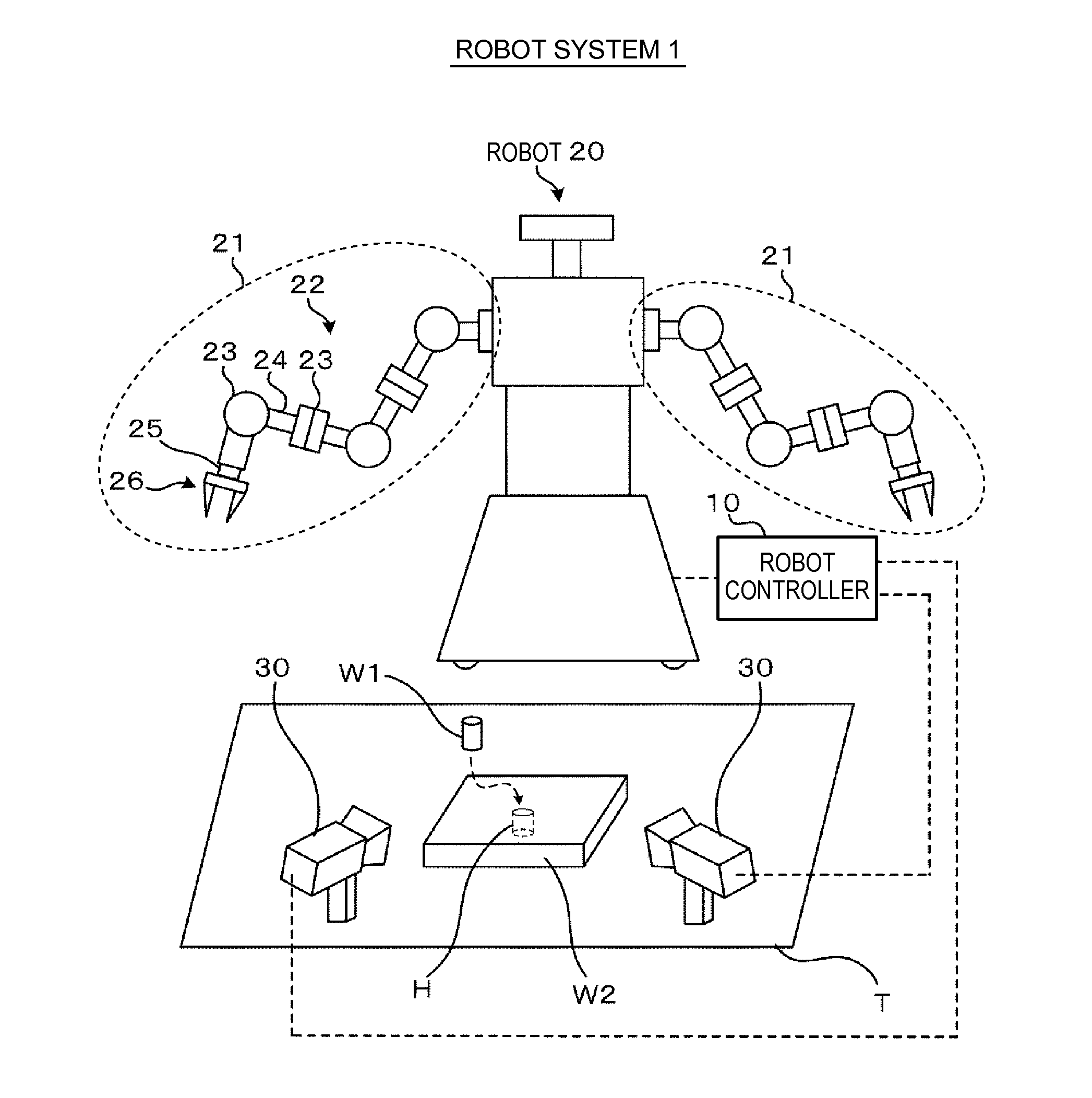
[0054]FIG. 1 shows an example of a schematic configuration of a robot system 1 according to the embodiment. As shown in FIG. 1, the robot system 1 includes a robot controller 10, a robot 20, and imaging devices 30. The robot controller 10 is communicably connected to the robot 20 and the imaging devices 30.
[0055]The robot controller 10 controls the entire robot 20. Further, the robot controller 10 controls imaging by the imaging devices 30.
[0056]The robot 20 moves according to a control signal from the robot controller 10 and performs an operation. The operation content is not particularly limited. For example, an operation of fitting a work W1 into a hole H of a work W2 on a working table T or the like is considered. The work may be called an object of operation.
[0057]The robot 20 has an arm 22 including one or more joints 23 and one or more links 24, a hand 26 provided on the distal end of the arm 22, and a forc...
second embodiment
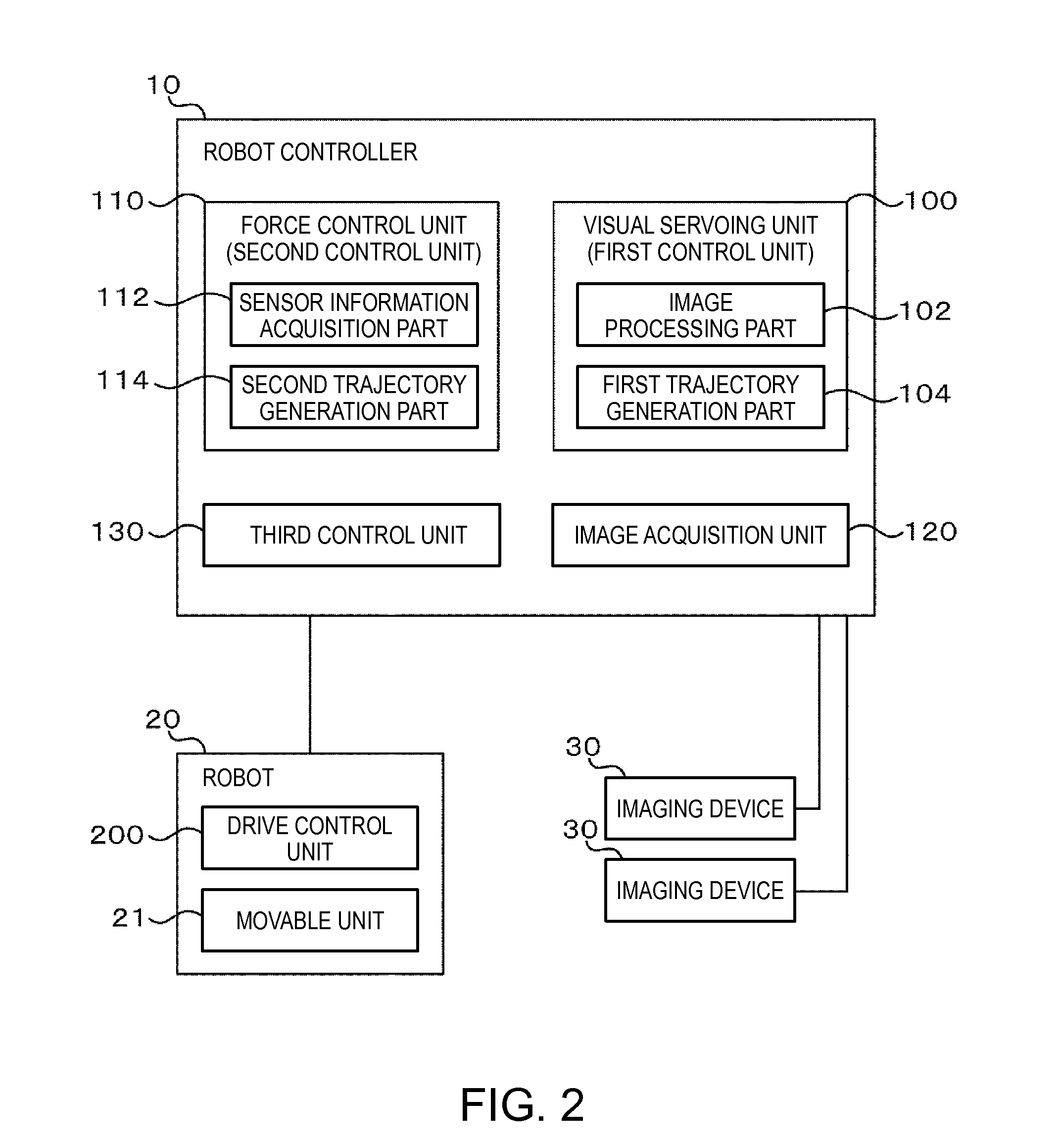
[0115]FIG. 11 shows an example of a function configuration of the robot system 1.
[0116]As below, the embodiment of the robot system 1 will be explained with reference to the drawing, and the explanation will be made with a focus on the differences from the above described embodiment and the explanation of the same items will be omitted.
[0117]The robot controller 10 has a main control unit 202, a position control unit 210, an impedance control unit 220, a visual servoing control unit 230, a sensor information acquisition unit 240, and an image acquisition unit 120.
[0118]The position control unit 210, the impedance control unit 220, and the visual servoing control unit 230 may be respectively referred to as “first control unit” and the main control unit 202 may be referred to as “second control unit”.
[0119]The main control unit 202 synchronizes the times of processing of calculating movement command values of the respective controls by the respective control units (position control un...
first modified example of second embodiment
[0211]In the embodiment, as shown in FIG. 12, the main body processing of the position control unit is executed with the synchronization signal T1 as the trigger. However, the main body processing of the position control unit 210 may be executed from the synchronization signal T2 to the immediately following synchronization signal T1. That is, the position control unit 210 executes the main body processing with the synchronization signal T2 as a trigger, and then, executes the output processing.
[0212]FIG. 21 is a flowchart showing an example of an operation of the position control unit according to the first modified example of the embodiment. In FIG. 21, the processing having the same signs as those in FIG. 17 have the same or similar functions as those of the processing in FIG. 17, and their detailed explanation will be omitted. The first modified example is different from the embodiment in that step S203A is executed in place of step S203 in FIG. 17 and step S206 in FIG. 17 is de...
PUM
 Abstract
Description
Claims
Application Information