Barrier-film forming apparatus, barrier-film forming method, and barrier-film coated container

a technology of barrier film and forming method, which is applied in the direction of packaging foodstuffs, transportation and packaging, packaged goods types, etc., can solve the problems of difficult to realize such a similar shape, inability to obtain the barrier property for practical use, and the non-uniformity of formed films is greatly increased. achieve the effect of high barrier property

Inactive Publication Date: 2015-04-23
MITSUBISHI HEAVY IND MACHINERY SYST LTD
View PDF2 Cites 1 Cited by
  • Summary
  • Abstract
  • Description
  • Claims
  • Application Information

AI Technical Summary

Benefits of technology

[0017]In the conventional techniques, there is a proposition (WO2003 / 101847) that provides an adequate clearance between an external electrode and a container. However, when the container has concaves and convexes, it is necessary to adjust the shape of the clearance from an approximately similar shape to be suited to the concave and convex portions of the container, thereby obtaining a shape that enables the container to be inserted into the clearance and have a high barrier property. Therefore, it is necessary to produce the external electrodes almost entirely to order to be adapted to diversified shapes of the containers, which increases costs and labors. The weight of the external electrode is easily increased, and thus arrangement of the external electrode or setting of a movable portion in the configuration of the apparatus is prone to be limited. Therefore, some trouble is caused in an apparatus that forms a film while a container is transported being inverted, for example.
[0020]To sum up, the problems are organized as follows. To form a high-quality gas barrier thin film, voltage to be applied to the inner face of the container, which will be explained later, needs to be uniformized. When an approach from a viewpoint of a structure of the external electrode is adopted, a combination of a space and a dielectric having appropriate size and composition is provided between the external electrode and the container, thereby optimizing voltage distribution. As described above, there is no conventional technique that achieves such a combination. If this combination can be achieved, various issues other than a high gas barrier property, specifically including sharing of the external electrode with various types of containers, handling of concave and convex designs of containers, uniform distribution of film thickness, and reduction in weight of the external electrode can be resolved. Therefore, significant effects can be achieved in terms of quality and device cost.
[0064]According to the present invention, the voltage to be applied to the entire inner face of the container can be uniformized by using the dielectric member installed between the external electrode and the container, and the clearance between the dielectric member and the container. Therefore, a barrier film formed on the inner face of the container can be entirely made uniform, thereby producing the container with a high barrier property.

Problems solved by technology

However, when the apparatus has a configuration in which the container is inserted longitudinally, it is difficult to realize such a similar shape.
In such cases, nonuniformity of the formed film is greatly increased, and therefore the barrier property for practical use cannot be obtained.

Method used


Image

  • Barrier-film forming apparatus, barrier-film forming method, and barrier-film coated container
  • Barrier-film forming apparatus, barrier-film forming method, and barrier-film coated container
  • Barrier-film forming apparatus, barrier-film forming method, and barrier-film coated container

Examples


first embodiment

[0104]A barrier-film forming apparatus according to a first embodiment of the present invention will be explained with reference to the accompanying drawings.

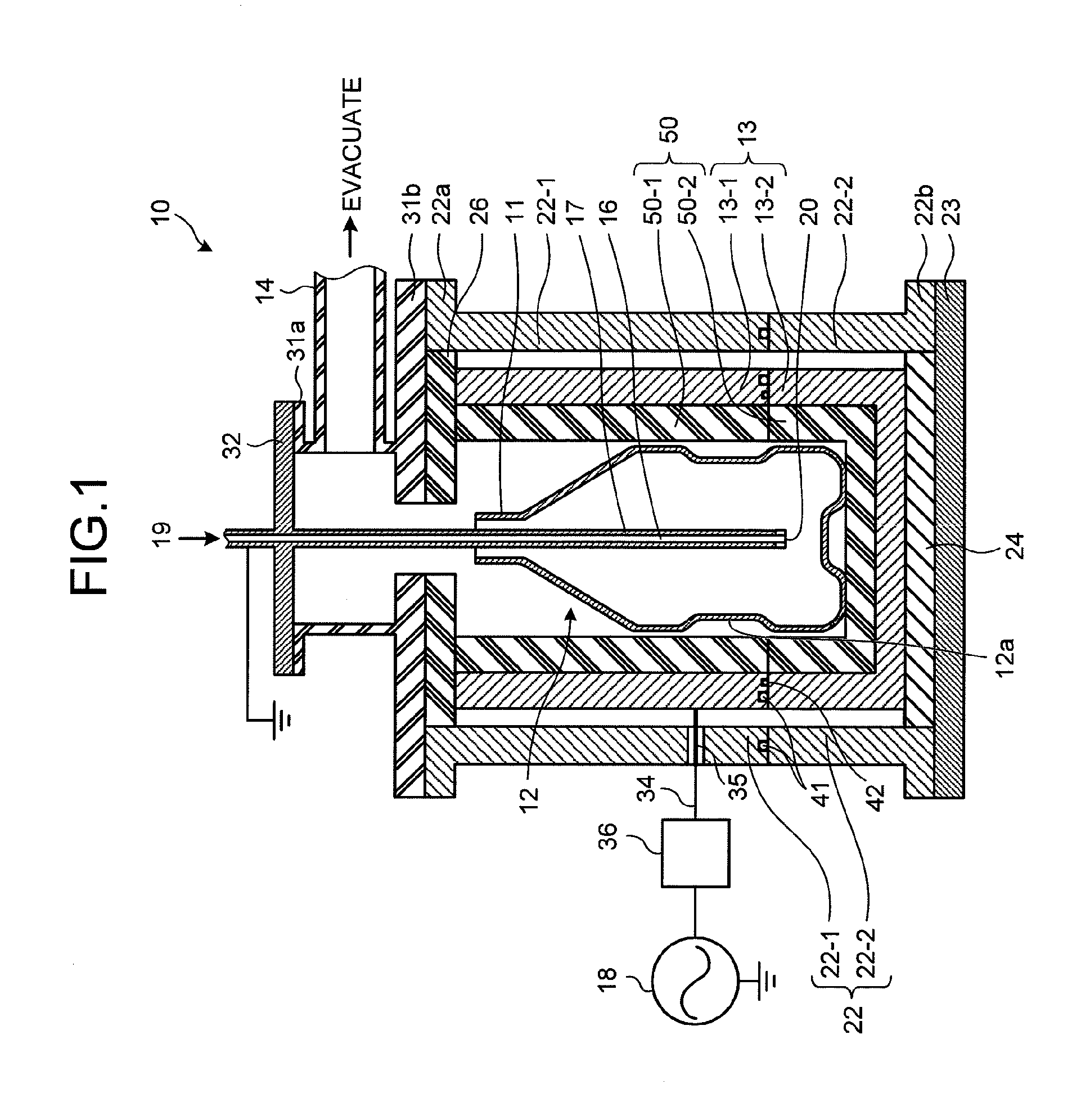
[0105]FIG. 1 is a conceptual diagram of the barrier-film forming apparatus according to the present embodiment. The same members as those in the barrier-film forming apparatus according to the conventional technique explained with reference to FIG. 38 are denoted by like reference numerals and redundant explanations thereof will be omitted.

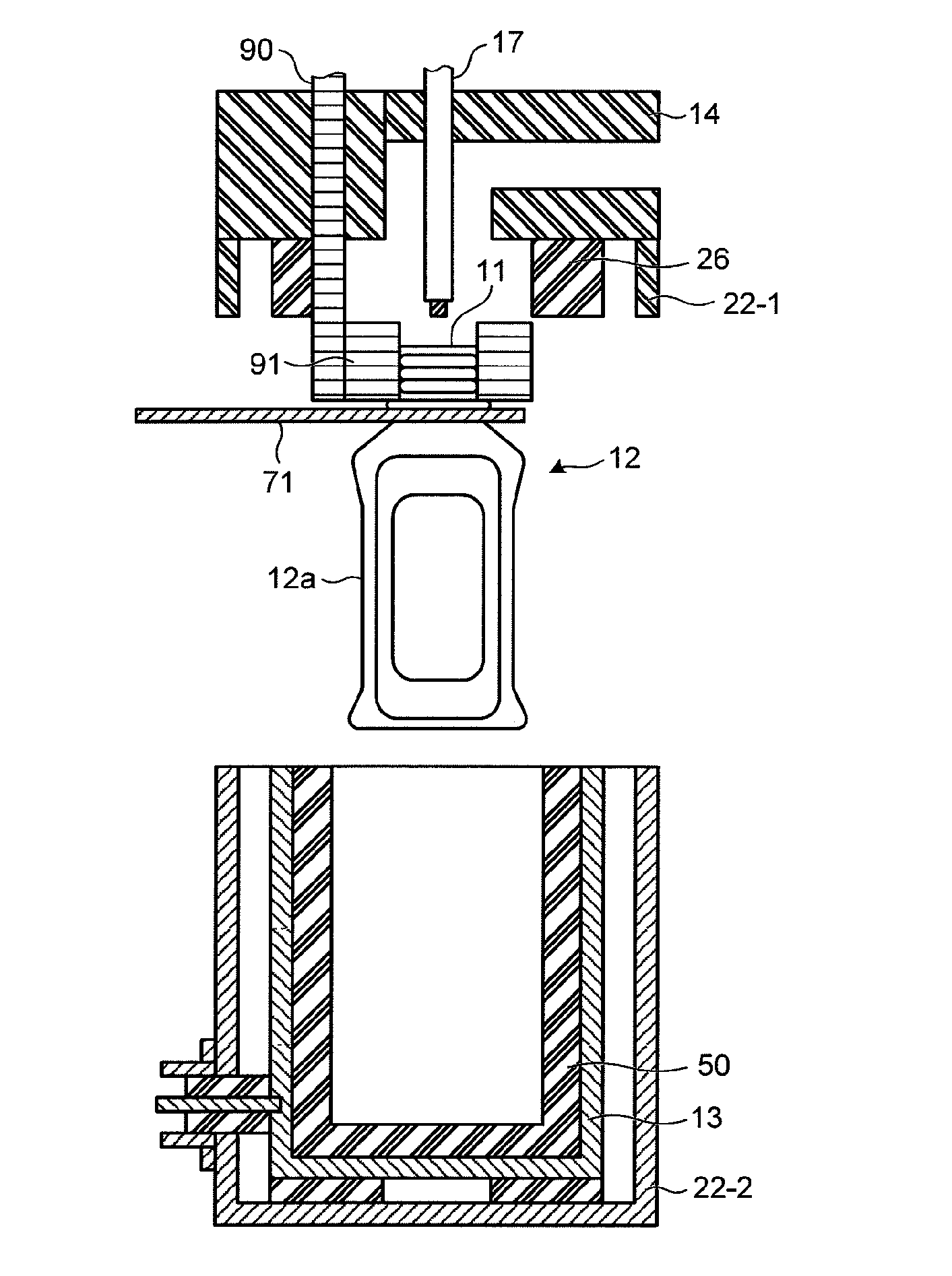
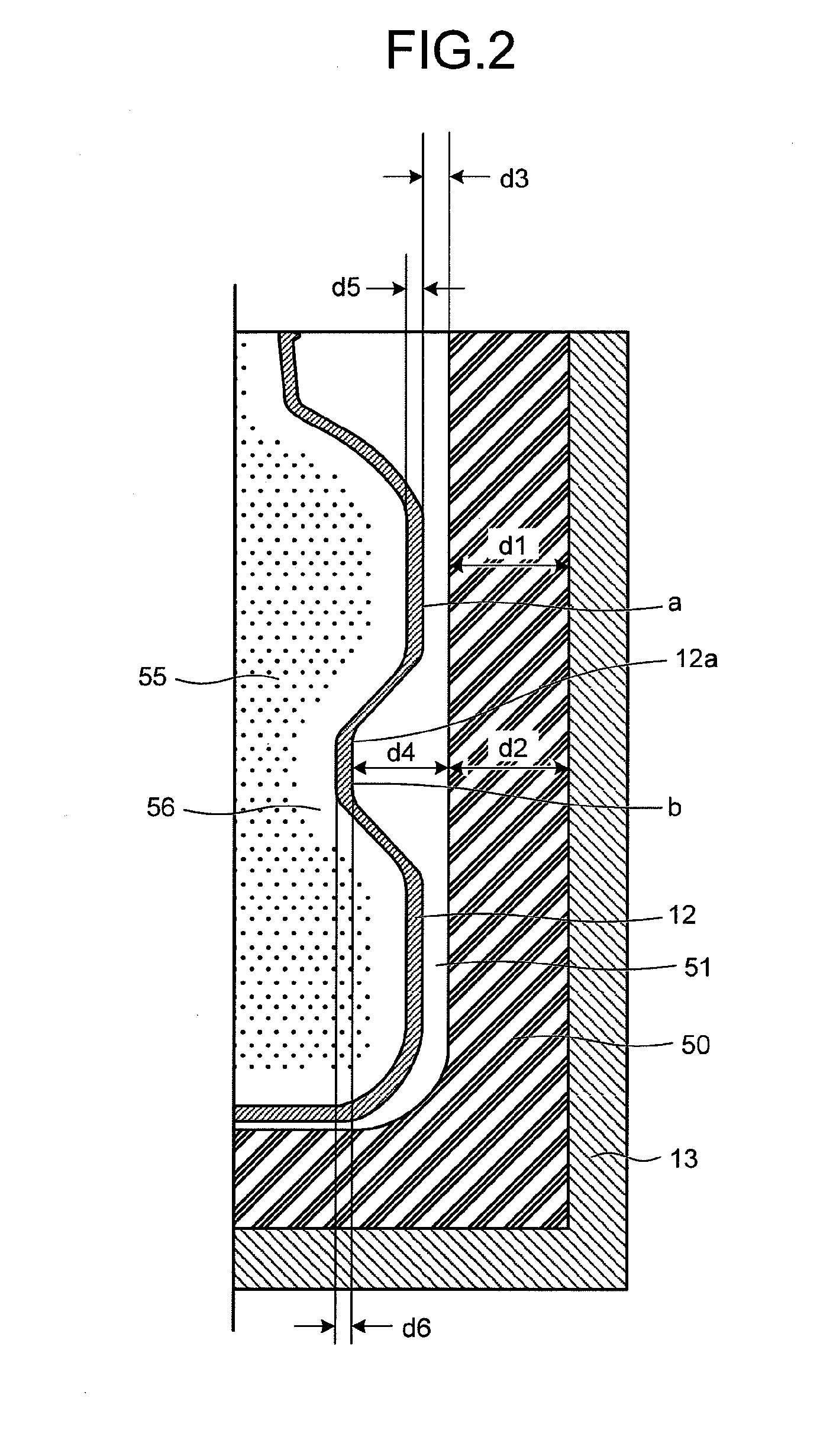
[0106]As shown in FIG. 1, a barrier-film forming apparatus 10 according to the present embodiment forms a barrier film on an inner face of a processing target, which is the plastic container (hereinafter, also “container”) 12 having at least one concave or convex portion 12a. The barrier-film forming apparatus 10 includes a dielectric member 50 that has a cavity sized to enclose at least a major portion of the container 12, the external electrode 13 that covers an outer circumference of the d...

second embodiment

[0229]FIG. 16 is a schematic diagram of a barrier-film forming apparatus according to another embodiment of the present invention.

[0230]As shown in FIG. 16, the shape of the container 12 is changed to have a circular cross section, and the clearance 51 is at least 3 millimeters.

[0231]According to the present embodiment, even when the clearance 51 between the dielectric member 50 and the container 12 is increased, a uniform and satisfactory film (having the BIF fifteen times higher or a higher BIF) can be formed on the inner face of the container.

third embodiment

[0232]FIG. 17 is a schematic diagram of a barrier-film forming apparatus according to still another embodiment of the present invention.

[0233]As shown in FIG. 17, the shape of the container 12 is changed to have a circular cross section, and the clearance 51 is at least 1 millimeter.

[0234]A dielectric member 62 of a convex shape corresponding to a concave portion 12b at the bottom of the container is further provided.

[0235]According to the present embodiment, uniform film formation can be achieved also at the concave portion 12b at the bottom of the container, as well as the concave portion 12a at the body of the container.


PUM

PropertyMeasurementUnit
flow rateaaaaaaaaaa
thicknessaaaaaaaaaa
widthaaaaaaaaaa

Abstract

A barrier-film forming apparatus that forms a barrier film on an inner face of a container having a concave or convex portion as a processing target, including: a dielectric member having a cavity sized to enclose the container, an external electrode covering an outer circumference of the dielectric member, an exhaust unit installed on an end face of the external electrode on a side where a mouth of the container is located, with an insulating member interposed therebetween, and depressurizing inside of the container through an exhaust pipe, an internal electrode inserted from a side of the exhaust pipe and also serving as a gas blowout unit that blows out medium gas for generating a barrier film into the container, and an electric-field applying unit that applies an electric field for generating exhaust between the external electrode and a ground electrode.

Description

BACKGROUND OF THE INVENTION[0001]I. Technical Field[0002]The present invention relates to a barrier-film forming apparatus, a barrier-film forming method, and a barrier-film coated container for uniformly forming a barrier film that provides a gas barrier property to a resin container, for example.[0003]II. Description of the Related Art[0004]Recently, an approach has been adopted to coat an inner face of a polyethylene terephthalate (PET) bottle, which is one type of plastic containers, with a film having a high barrier property, for example a carbon film such as diamond-like carbon (DLC) or a silica film, to prevent transmission of external oxygen or transmission of internal carbon dioxide (for example, from carbonated beverage). Various film depositing apparatuses for that purpose are proposed (Japanese Patent Application Laid-open No. H8-53116, Japanese Patent No. 2788412 (Japanese Patent Application Laid-open No. H8-53117), WO2003 / 101847, Japanese Patent No. 3643813 (Japanese P...

Claims


Application Information

Patent Timeline
Patent Type & Authority Applications(United States)
IPC IPC(8): C23C16/503B65D25/14
CPCB65D25/14C23C16/503B65D23/02C23C16/045C23C16/509H01J37/32348H01J37/32623C23C16/50
Inventor ASAHARA, YUJIYAMAKOSHI, HIDEODANNO, MINORUGOTO, SEIJISHIRAKURA, AKIRANAKAYA, MASAKIHIROYA, KIYOSHI
Owner MITSUBISHI HEAVY IND MACHINERY SYST LTD
Why Eureka
Try Eureka