
Condenser microphone

Active Publication Date: 2015-04-23
AUDIO-TECHNICA
View PDF2 Cites 0 Cited by
  • Summary
  • Abstract
  • Description
  • Claims
  • Application Information

AI Technical Summary

Benefits of technology

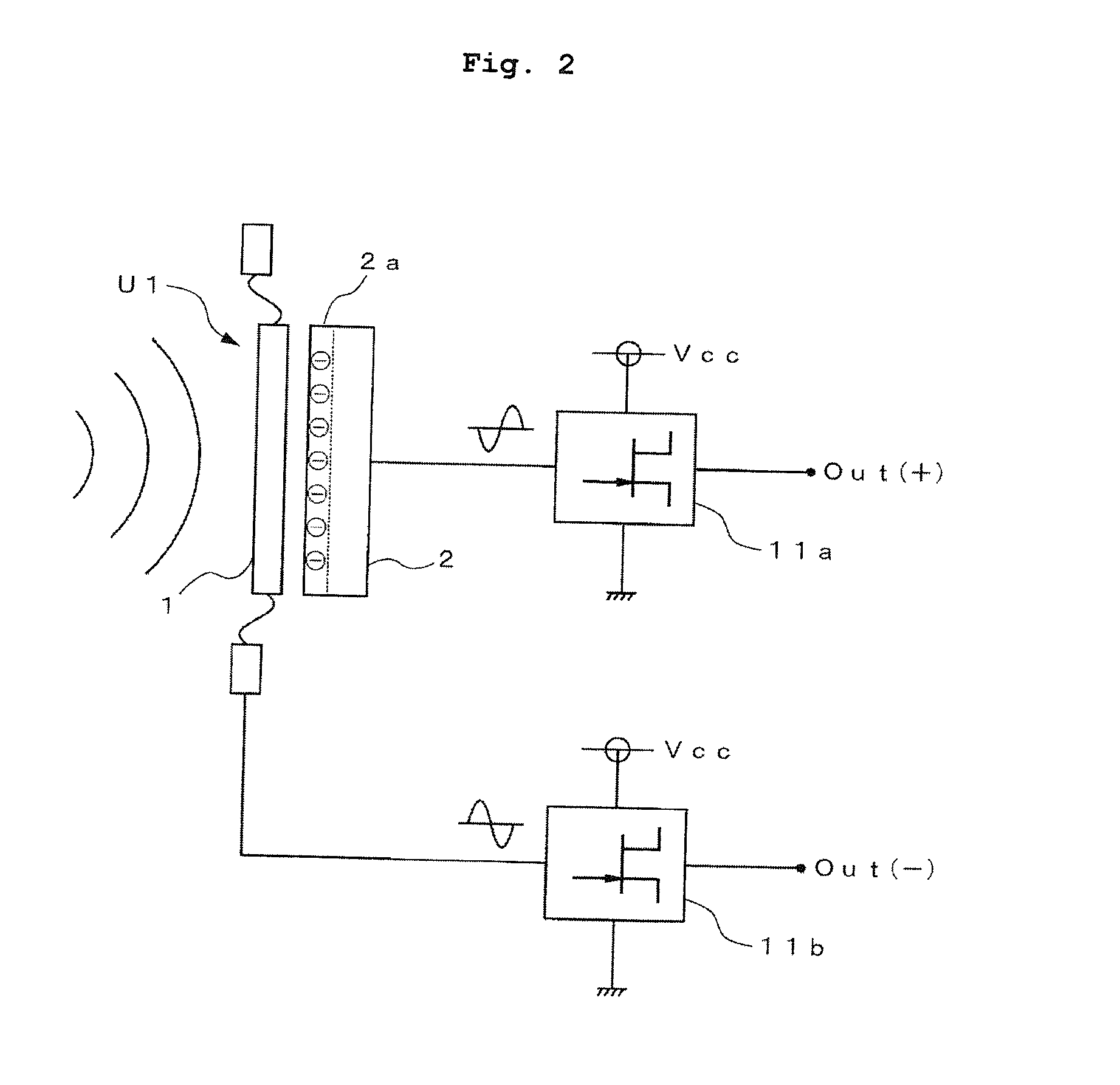
The invention is a new type of condenser microphone that solves problems with traditional microphones. It provides a balanced output of audio signals with opposite phases, which helps to cancel out external noise and improve the quality of the audio signal. This happens because the microphone unit has a diaphragm and a fixed electrode that create an off-center electric field, which affects the audio signals in a way that can be reversed and balanced. This design makes it easier to achieve high signal-to-noise ratios and ensures a good quality audio signal.

Problems solved by technology

In addition, according to the structure illustrated in FIG. 6, because the inversion audio output is generated through the inverter circuit 13, unbalance of signals by a difference of signal transmission systems occurs between the inversion audio output and a non-inversion audio output not transmitted through the inverter circuit 13, which results in causing a quality of the audio signals to be deteriorated.
In addition, according to the structure illustrated in FIG. 7, entire performance of the microphone is limited by a unique frequency characteristic or a distortion characteristic of the transformer T1, and the transformer T1 increases a cost.

Method used


Image

  • Condenser microphone
  • Condenser microphone
  • Condenser microphone

Examples


Embodiment Construction

[0045]A condenser microphone according to the present invention will be described on the basis of embodiments illustrated in the drawings.

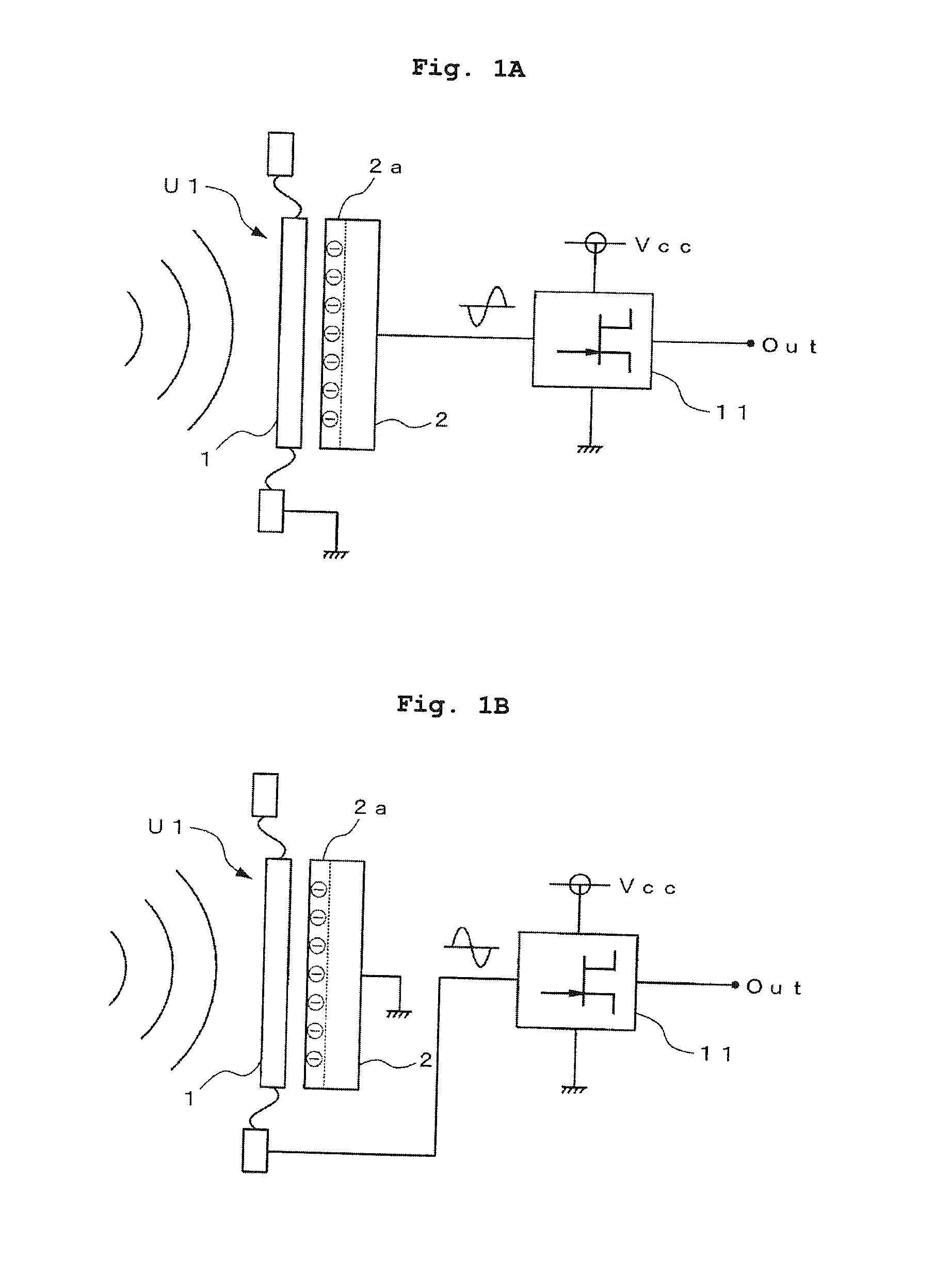
[0046]As described above, in a condenser microphone unit, a diaphragm is arranged to opposite a fixed electrode and a condenser is formed between the diaphragm and the fixed electrode. FIGS. 1A and 1B illustrate an example of a condenser microphone unit U1 of an electret type including an electret dielectric film 2a in which negative charges are charged, at the side of a fixed electrode 2 facing a diaphragm 1.

[0047]In the example illustrated in FIGS. 1A and 1B, a charge amount Q by the electret dielectric film 2a is constant and a change in capacitance C of the condenser microphone unit U1 receiving a sound pressure changes a voltage according to a relation of Q=C×V (V is a voltage between both poles of a condenser).

[0048]In addition, in the condenser microphone unit U1 illustrated in FIGS. 1A and 1B, when a positive sound pressure is received in ...


PUM


Abstract

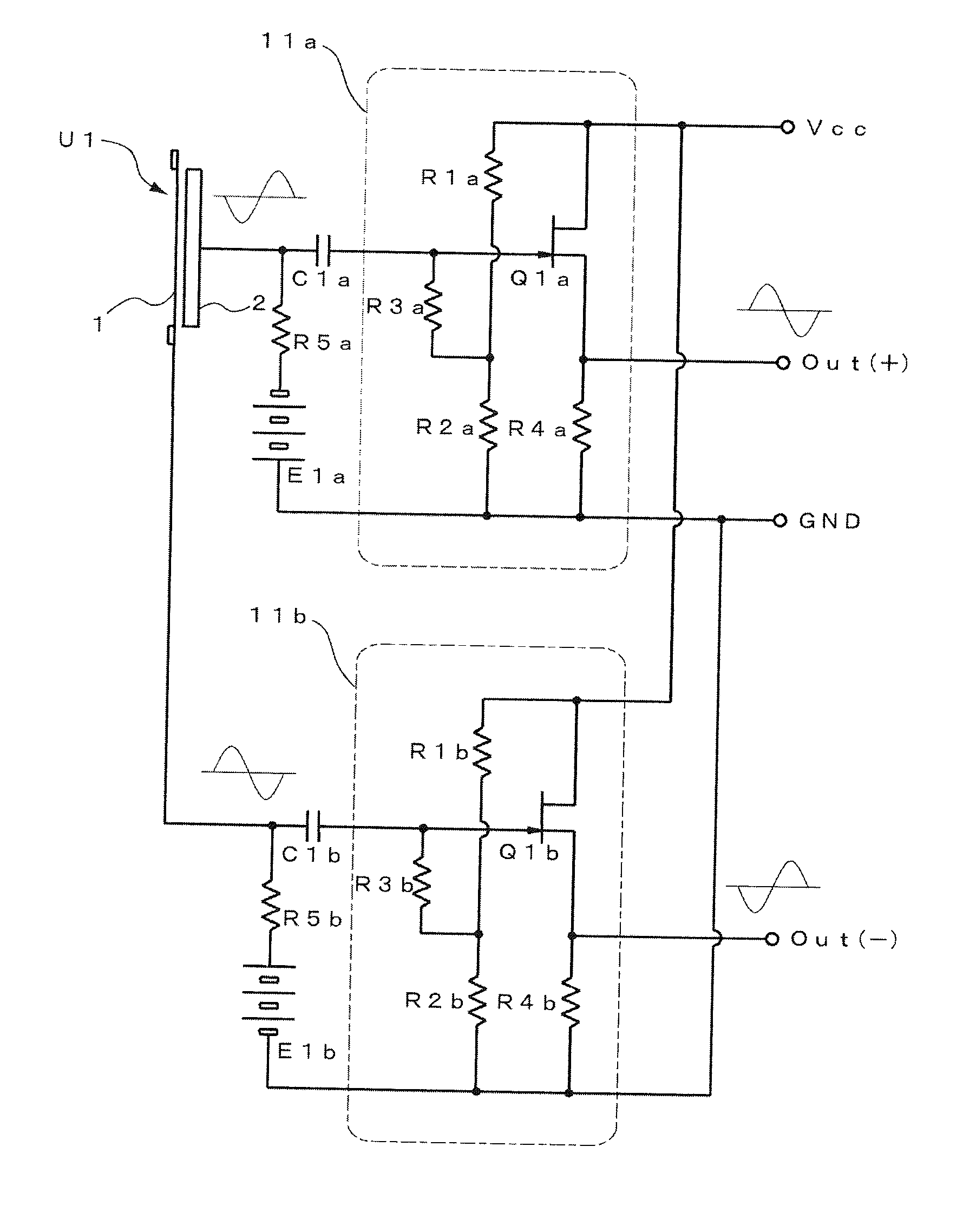
A condenser microphone that provides a balanced output of audio signals from initial steps of a diaphragm and a fixed electrode is provided. The condenser microphone includes: a condenser microphone unit including a diaphragm being arranged opposite a fixed electrode; a first impedance converter being connected to the fixed electrode of the condenser microphone unit and outputting a first electric signal generated in the fixed electrode; and a second impedance converter being connected to the diaphragm of the condenser microphone unit and outputting a second electric signal generated in the diaphragm. By this structure, balanced outputs of the audio signals having phases reverse to each other are provided by the first and second impedance converters immediately after the condenser microphone unit.

Description

BACKGROUND OF THE INVENTION[0001]1. Field of the Invention[0002]The present invention relates to a condenser microphone that provides a balanced output of an audio signal by a condenser microphone unit configured by a diaphragm and a fixed electrode.[0003]2. Description of the Related Art[0004]In a condenser microphone, an audio signal is generated on the basis of a change in capacitance between a diaphragm and a fixed electrode opposite to each other.[0005]That is, a condenser microphone unit obtained by arranging the diaphragm opposite the fixed electrode is configured to extract the audio signal using an impedance converter by a field effect transistor (FET), for example, because output impedance is very high, when the capacitance is about several tens of picofarad (pF).[0006]When the condenser microphone unit is connected to the impedance converter, a circuit structure in which one of the fixed electrode and the diaphragm is connected to a reference potential point (ground line)...

Claims


Application Information

Patent Timeline
IPC IPC(8): H04R3/00H04R1/08
CPCH04R1/08H04R3/00H04R19/016H04R19/04
Inventor OKITA, SHIOTO
Owner AUDIO-TECHNICA
Learn More