Ceramic Capacitors with Improved Lead Designs

a ceramic capacitor and lead design technology, applied in the direction of fixed capacitors, stacked capacitors, fixed capacitor details, etc., can solve the problems of increasing the potential for cracks, electrical failure, cracks in ceramic capacitors, etc., to reduce the stresses on ceramic elements, increase mechanical robustness, and increase mechanical robustness

a ceramic capacitor and lead design technology, applied in the direction of fixed capacitors, stacked capacitors, fixed capacitor details, etc., can solve the problems of increasing the potential for cracks, electrical failure, cracks in ceramic capacitors, etc., to reduce the stresses on ceramic elements, increase mechanical robustness, and increase mechanical robustness

US20150114697A1Inactive Publication Date: 2015-04-30KEMET ELECTRONICS CORP

Image

  • Ceramic Capacitors with Improved Lead Designs
  • Ceramic Capacitors with Improved Lead Designs
  • Ceramic Capacitors with Improved Lead Designs

Examples


example 1

[0074]A comparative example was prepared with a flat lead with a width of 1.8 mm (0.071 inches) without perforation or protrusion connected along the length of each MLCC of a stack of four MLCC's using 10 mg of solder paste for each lead MLCC interface.

example 2

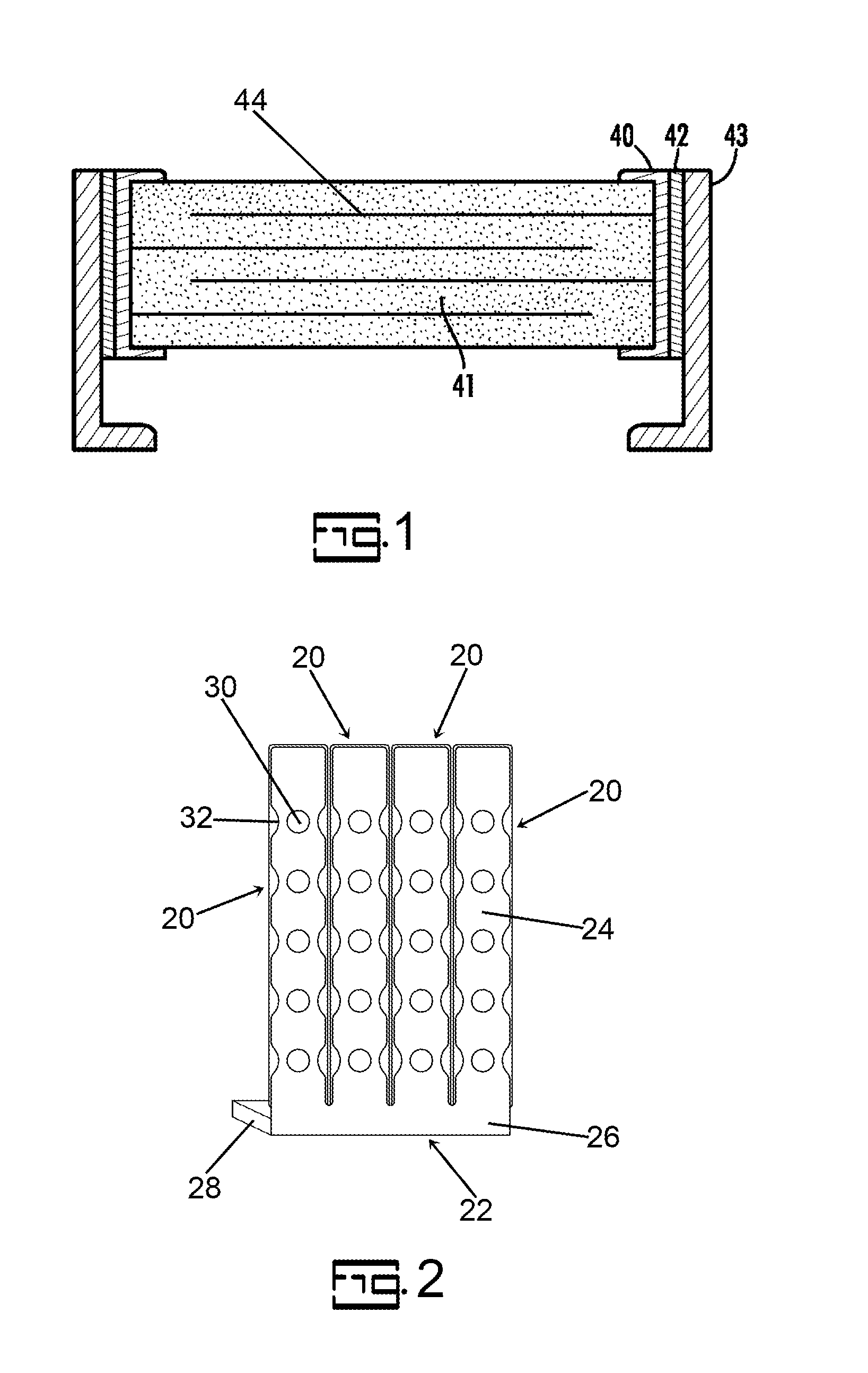
[0075]A lead with edge indentations was manufactured and connected along the length of each MLCC using 10 mg of solder paste for each lead MLCC interface. The lead width was 1.8 mm (0.071 inches) with 5 edge indentations per edge that were half circles with a radius of 0.71 mm (0.028 inches) separated by about 2.2 mm (0.085 inches) with the group of 5 perforations approximately centered on the MLCC terminal. The edge indentations, 32, are illustrated schematically in FIG. 2.

example 3

[0076]A crimped lead with protrusions was manufactured and connected along the length of each MLCC using 26 mg of solder paste for each lead MLCC interface. The lead width was 1.80 mm (0.071 inches) with 4 crimps per lead each having a width of about 0.38 mm (0.015 inches) where the lead contacted the capacitor terminal and arranged in two pairs of crimps oriented perpendicular to the length of the lead. The crimps within each pair were separated from each other by 1.8 mm (0.071 inches) and the center of each pair of crimps were separated from each other by about 10.2 mm (0.40 inches). The crimps extended from edge to edge of the lead. The height of each crimp was about 0.15 mm (0.006 inches). The pairs of crimps were located in the approximate center of the MLCC electrode terminals. The device is illustrated in FIG. 16.


PUM

PropertyMeasurementUnit
Lengthaaaaaaaaaa
Lengthaaaaaaaaaa
Lengthaaaaaaaaaa

Abstract

An electronic component is provided with improved thermal stability. The electronic component comprises at least one capacitive element wherein the capacitive element comprises internal electrodes of alternating polarity separated by a dielectric. External terminations with a first external termination of the external terminations are in electrical contact with internal electrodes of a first polarity and a second external termination of the external terminations are in electrical contact with internal electrodes of a second polarity. A first external lead frame is in electrical contact with the first external termination with a conductive bond there between wherein the first external lead frame comprises at least one feature selected from the group consisting of a perforation, a protrusion and an edge indentation.

Description

CROSS-REFERENCE TO RELATED APPLICATIONS[0001]This application claims priority to pending U.S. Provisional Patent Appl. No. 61 / 896,818 filed Oct. 29, 2013 which is incorporated herein by reference.BACKGROUND[0002]The present invention is related to improvements in lead frames and lead frame bonding wherein the improvements mitigate fatigue cracking in the bond related to thermal cycling. Furthermore in the case of ceramic components such as multilayer ceramic capacitors (MLCC) the present invention mitigates the formation of stress cracks in the ceramic capacitor in addition to the bonding material.[0003]In recent years, chip-type multilayer ceramic capacitors have come into general use for mounting directly to a substrate. However, if the substrate is deformed by deflection, a mechanical stress is transferred to the multilayer ceramic capacitor which may cause a crack to form in the ceramic capacitor. This potential for a crack increases as the size of the capacitor increases due to...

Claims


Application Information

Patent Timeline
30 Apr 2015
Publication
US20150114697A1
IPC
H01L23/495; H01L23/498; H01G4/30; H01G4/248; H01G4/12
CPC
H01L23/49589; H01G4/248; H01G4/12; H01L23/49582; H01L23/49861; H01L23/49565; H01G4/30; H01G4/232
Inventors
MURRELL, JEFFREY S.; JONES, LONNIE G.