
System for the Monitoring and Maintenance of Remote Autonomously Powered Lighting Installations

a technology for autonomous lighting and monitoring and maintenance, which is applied in the direction of parallel operation of dc sources, power supply testing, three-or-more wire dc circuits, etc., can solve the problems of inefficient or unnecessary light pole repairs, unique problems of remote solar and/or wind powered lighting installation, etc., to reduce the operation time and/or intensity of loads, reduce re-charging, and reduce the effect of lumen outpu

Active Publication Date: 2015-04-30
CLEAR BLUE TECH
View PDF0 Cites 16 Cited by
  • Summary
  • Abstract
  • Description
  • Claims
  • Application Information

AI Technical Summary

Benefits of technology

The patent describes a system that controls the output of solar lights and wind turbines based on factors like short-term weather data and seasonal environmental factors. The system can adjust the output of the loads to increase power output during periods of increased wind or reduce the overall load intensity during periods of reduced sunlight exposure. The technical effect of this system is to optimize the efficiency and performance of solar energy installations by adjusting the output of the loads to match the varying environmental factors, resulting in brighter lighting, longer periods of operation, and overall improved performance.

Problems solved by technology

The applicant has appreciated, however, that by their nature, the installation of remotely located solar and / or wind powered lighting and other autonomously powered installations presents a unique problem from the point of view of servicing.
As a result, light pole repairs are often undertaken which are either inefficient or unnecessary where, for example, low power output or insufficient battery charge results from environmental conditions, such as prolonged periods of cloud cover, or dirt or other organic growth covering photovoltaic cells or other electricity generating components.

Method used


Image

  • System for the Monitoring and Maintenance of Remote Autonomously Powered Lighting Installations
  • System for the Monitoring and Maintenance of Remote Autonomously Powered Lighting Installations
  • System for the Monitoring and Maintenance of Remote Autonomously Powered Lighting Installations

Examples


Embodiment Construction

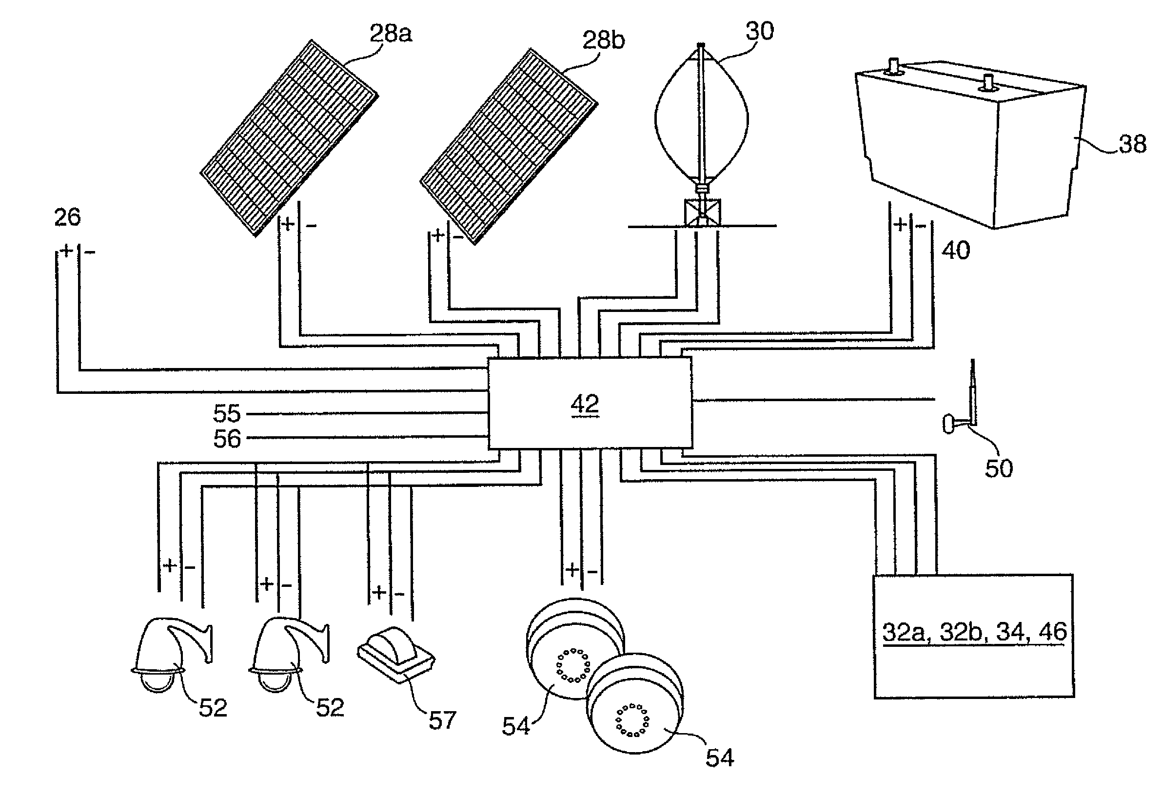
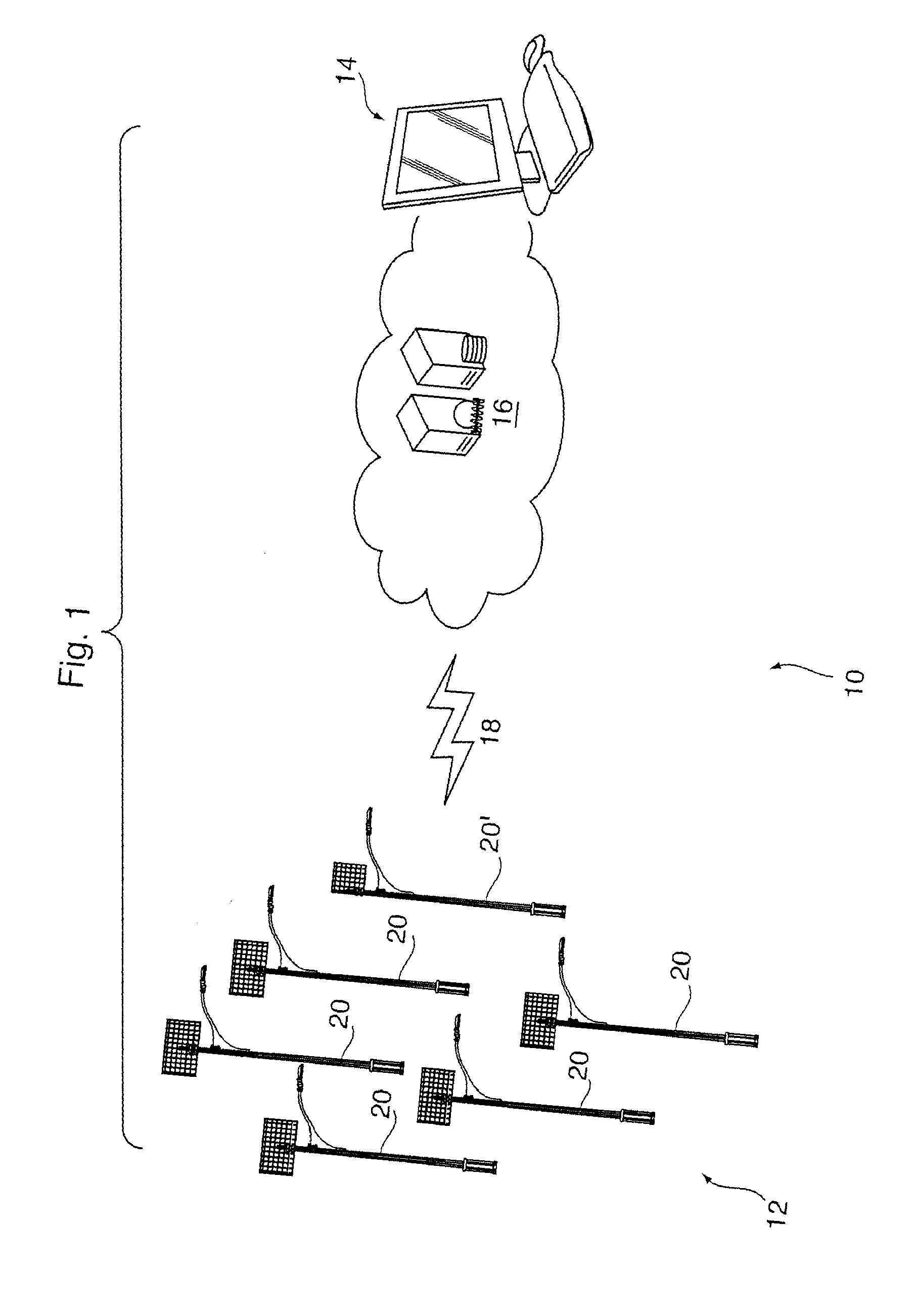
[0058]Reference may be had to FIG. 1 which illustrates schematically a monitoring, control and maintenance system 10 for remotely located autonomously powered lighting, security / video, monitoring (weather, environmental (including pollution), industrial (flow, sewage, water) or telecommunications (cellular, WiFi, etc.) installation systems. In the embodiment shown, the system 10 includes an autonomously powered light pole array 12, a central processing unit (CPU) 14 for receiving operational data signals from and providing central signals to the array 12 and a data storage repository 16. The light pole array 12, central processing unit 14 and data storage repository 16 are most preferably provided in wireless electronic communication by a suitable cellular, Zigbee or WiFi communications network 18.

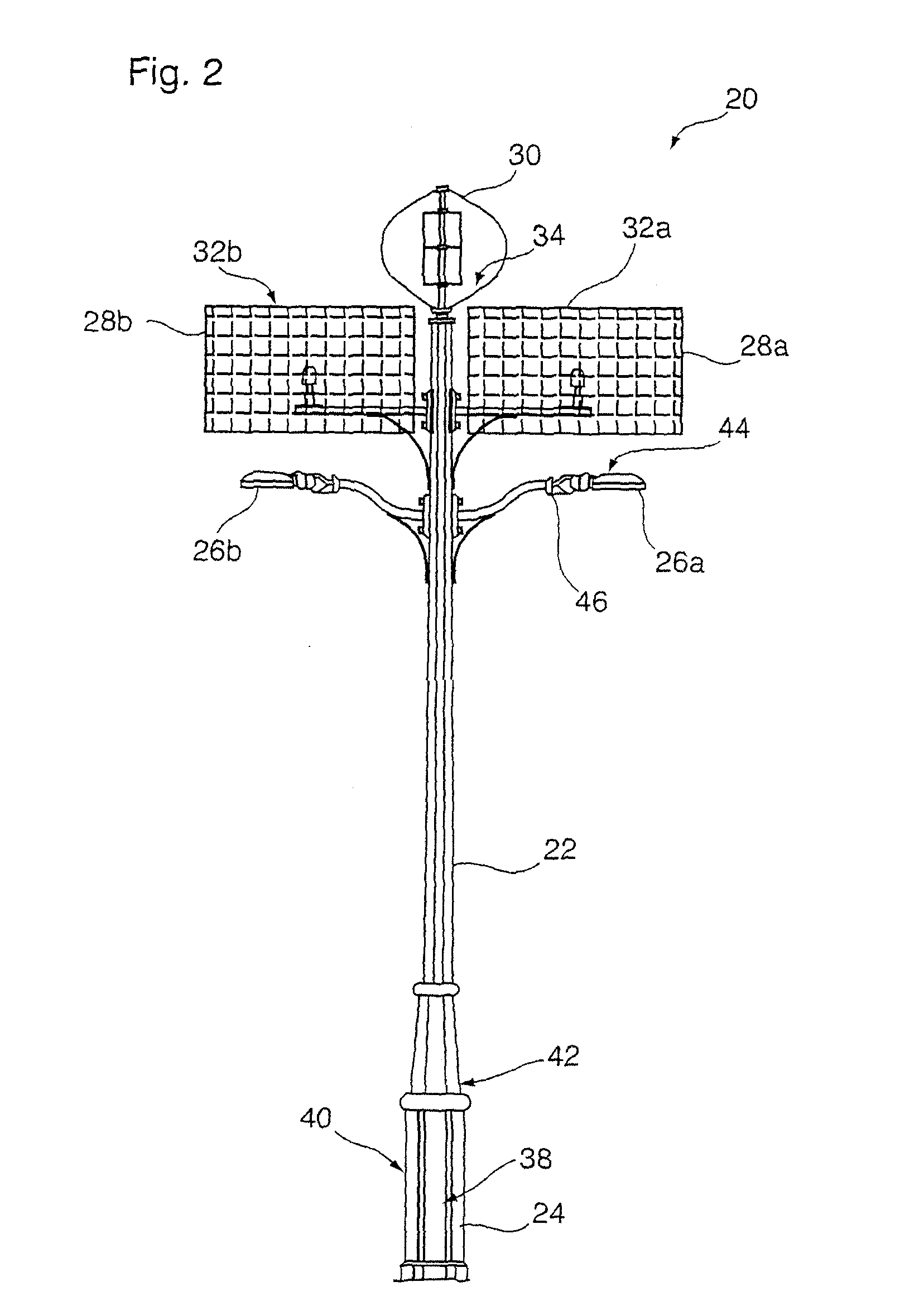
[0059]The light pole array 12 preferably consists of a number of autonomously powered light poles 20 which are installed for operations at a geographic location remote from the CPU 14. The...


PUM


Abstract

A system of monitoring and / or maintaining remotely located autonomously powered lights, security systems, parking meters, and the like is operable to receive data signals from a number of the devices, and provide a comparison with other similar devices in the same geographic region to detect a default condition of a particular device, and / or assess whether the defect is environmental or particular to the specific device itself. The system includes memory for storing operating parameters and data, and outputs modified control commands to the devices in response to sensed performance, past performance and / or self-learning algorithms. The system operates to provide for the monitoring and / or control of individual device operating parameters on an individual or regional basis, over preset periods.

Description

RELATED APPLICATIONS[0001]This application is a continuation-in-part of a U.S. patent application Ser. No. 13 / 507,318, filed 21 Jun. 2013.SCOPE OF THE INVENTION[0002]The present invention relates to a system for the remote monitoring of an autonomous power generating apparatus, and more particularly a system for the monitoring and maintenance of remote lighting and / or security or video installations which may be photovoltaic, wind turbine and / or other direct current source powered.BACKGROUND OF THE INVENTION[0003]The use of powered lighting installations is becoming more and more prevalent. Such installations have proven highly effective, particularly when used in remote locations where conventional electrical grid access is not commercially feasible.[0004]Various third parties, such as U.S. Patent Publication No. US 20100029268 A1 to Myer, published 4 Feb. 2010, have disclosed systems for monitoring and controlling solar powered light installations remotely. In the system developed...

Claims


Application Information

Patent Timeline
Patent Type & Authority Applications(United States)
IPC IPC(8): H02J13/00H02J7/00H02J7/35H05B37/02H02J15/00
CPCH02J13/00H05B37/0227H02J7/007H02J15/00H02J7/35H05B37/0272Y04S40/12G01R31/40H02J1/08H02J1/10H05B47/22H05B47/105H05B47/19H02J2300/40H02J13/00002H02J2310/12H02J2300/28H02J3/381H02J13/00016H02J13/00026H02J13/00004H02J13/00006Y02B90/20Y02E10/76H05B47/175H05B47/115H05B47/17H02J7/04H02J13/00022Y04S10/123Y04S20/246Y02B70/30Y02E40/70Y04S40/124Y04S40/126G01R31/088
Inventor TUERK, JOHNTUERK, MIRIAMWINDRIM, MARKYAFAOUI, AHMAD
Owner CLEAR BLUE TECH
Learn More