Micro-current sensing auto-adjusting heater system for eye-shield

a heater system and micro-current technology, applied in the field of heating systems, can solve the problems of affecting the use of goggle eye shields, and not providing customized heating of lenses, etc., to achieve greater user control over the goggle eye shield, facilitate calculations, and constant heat

Active Publication Date: 2015-05-07
ABOMINABLE LABS LLC +1
View PDF5 Cites 17 Cited by
  • Summary
  • Abstract
  • Description
  • Claims
  • Application Information

AI Technical Summary

Benefits of technology

[0037]Alternatively, in accordance with this aspect of the invention, the eye-shield condensation system further comprises a look-up table of heating element resistance values each associated with a corresponding plurality of pulse-width adjustment factors. This table facilitates calculations by the microcomputer for an appropriate adjustment to be applied to the at least one pulse-width modulator. This adjustment by the microcomputer compensates for variations in resistance encountered from at least one of one eye-shield region to another eye-shield region and one eye-shield to another eye-shield.
[0038]Still further, alternatively, in accordance with this aspect of the invention, there is provided a plurality of eye-shield condensation prevention systems, wherein a first of the eye-shield condensation prevention systems is used to enable pulse-width modulator duty cycle adjustments to maintain constant heat from at least one heating element of the first of the plurality of eye-shield condensation prevention systems relative to the at least one heating element of a second of the plurality of eye-shield condensation prevention systems, despite variations of heater resistance values from the first eye-shield condensation prevention system and the second eye-shield condensation prevention system. This aspect of the invention provides for consistent heating to be applied, despite variations in thickness of a thin-film heating element that is applied to the eye-shield, from one eye-shield region to another eye-shield region, and one eye-shield to another eye-shield. This aspect of the invention also addresses the issue of hot spots that occur on an eye-shield due to inconsistent thicknesses and resistances of a thin-film heating element, allowing for consistent heating across the entire surface of a goggle eye-shield by adjusting the overall amount of power that is supplied to an eye-shield. This allows for greater user control over the goggle eye-shield, letting the user set a temperature or setting that is consistent from one eye-shield to another eye-shield.

Problems solved by technology

When the temperature of such an eye-shield has dropped below a dew-point temperature, i.e., the atmospheric temperature below which water droplets begin to condense and dew can form, fogging has occurred and has obstructed vision.
Fogging that impairs vision is a common problem with such goggles, dive masks and eye-protecting shields.
However, without apportionment of the heater on the irregularly-shaped eye-shield lenses of these apparatus, such eye-shields have been subject to problems of creating hot spots on the irregularly-shaped lenses and have not provided for customizable heating of the lenses.
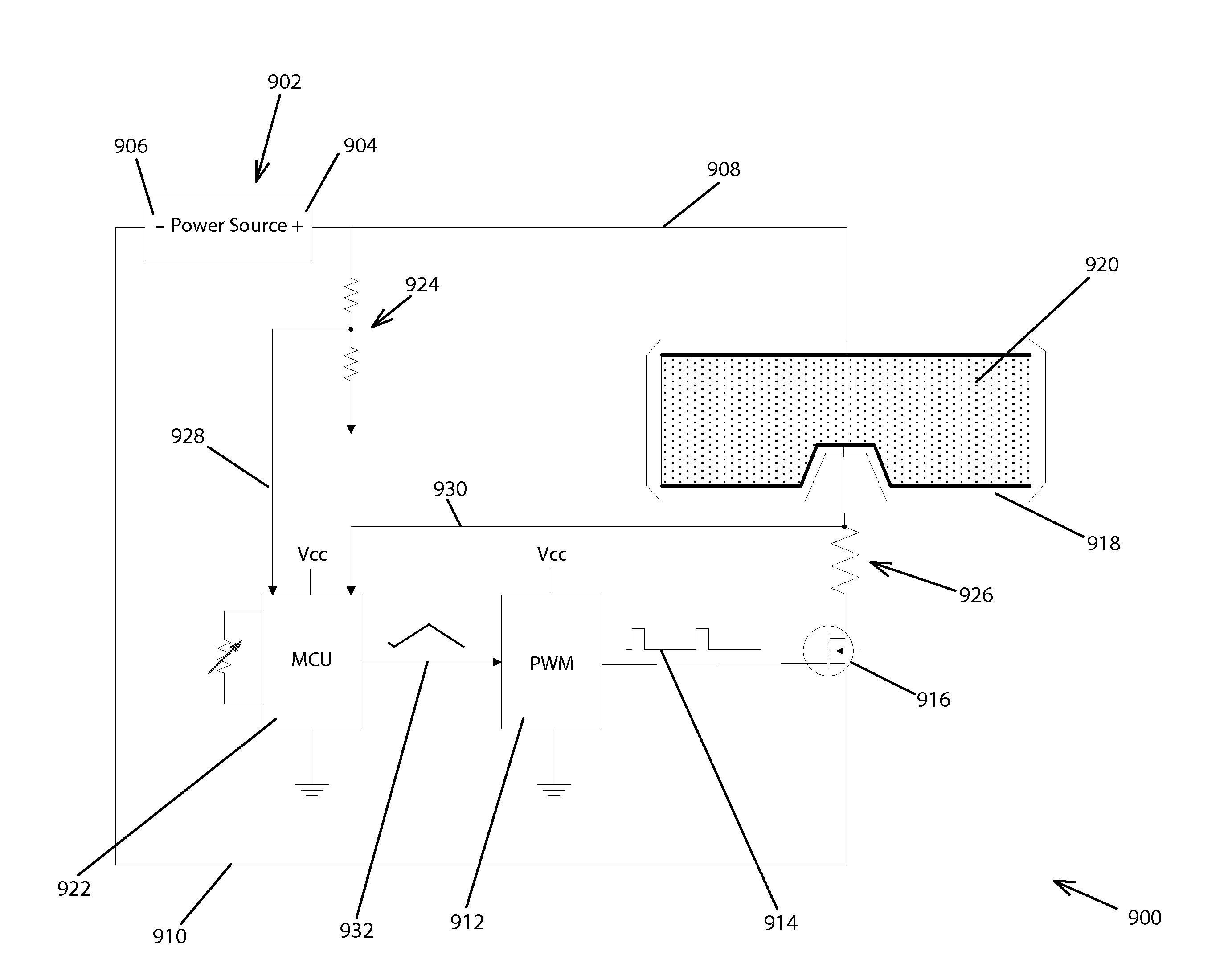
This newer system has made use of apportioned heaters on an eye-shield, but there has developed the potential problem that the resistivity of the heater from one portion of the heater to another portion of the heater on the eye-shield may be different, and this would also lead to variations in heating across the eye-shield.
Further, an additional problem associated with a thin-film heater for eye-protecting shields has been the variations of resistance in the heaters encountered from one eye-shield to another eye-shield.
Accordingly, the undesirable effects on even, uniform, or otherwise expected, heating, resulting from varied resistance of a thin-film heater across an eye-shield, or from one eye-shield to the next, had not been appreciated until the Parent application and the PWM application had been implemented.
These variations of resistance have resulted primarily from difficulties experienced in applying the thin-film heating elements uniformly across the eye-shield surfaces, and from difficulties experienced in applying the thin-film heating elements consistently uniformly from one eye-shield to another.
Thus, the uneven and inconsistent application of thin film heating elements has created variations in resistivity across the eye-shield regions, and as a result, variations in heat supplied by the thin-film heaters on the respective eye-shield regions.
Either way, the problem is the same which has led to uneven, or otherwise undesirable, heating characteristics.
Accordingly, Curcio likewise does not teach even and consistent heating of multiple regions of a single lens.
However, Reuber et al. does not disclose even heating of a lens, or alternatively customized heating of the lens in accordance with a heating profile, by employing a certain configuration of apportioned thin-filmed heating material on the lens.
Still further, Reuber does not teach even and consistent heating of one region of an eye-shield to the next region of the same eye-shield, or consistent heating among multiple eye-shields, through the use of an apportioned thin-film heater.
Thus, variations in the thickness of thin-film heaters applied to heat eye-shields to prevent fogging have led to uneven heating over the entire surface of an irregular-shaped eye-shield, and in particular over multiple regions of a single irregular-shaped eye-shield or multiple irregular-shaped eye-shields.
Similarly, the prior art has not disclosed even and consistent heating of one region of an eye-shield relative to another region of the same eye-shield, or consistent heating from one eye-shield to the next, despite variable thicknesses of thin-film elements used.
The goggle of Lebel et al. would be susceptible to hot spots, and therefore using such a device in a limited battery-powered application would have unduly discharged the battery.
For example, where the terminals are on either side of the lens in a resistive wiring application, there have been problems with evenly heating the lens since the distance the wire has had to travel from one terminal to the other has been greater for those wires traveling over the bridge of the nose and down under the eyes than other wires that travel the shorter distance across a central portion of the lens.
To overcome fogging conditions enough power must be applied to overcome the fog in the areas with the greatest distance between the terminal connection points, causing the shorter distance areas to overheat, which in turn has wasted power.
Thus, the problem has resulted in limited usefulness of heating of goggle eye-shields.
Because of the irregular shape of eye-shields, these problems have existed whether one has considered resistive-wire applications or resistive-film applications.
Still another problem associated particularly with goggles and dive masks is the amount of space provided between the eye-shield portion of the device and the user's face.
Further, where excess distance has been provided between the shield portion of the device and the user's eyes, the ability to incorporate corrective lenses into the goggle or mask eye-shield itself has been prohibited.
Increased distance between the user's eyes and the eye-shield has improved anti-fogging capability in typical air-flow dependent anti-fog goggles, however, locating the eye-shield at such a great distance from the user's eyes to facilitate anti-fogging has made corrective goggle lenses ineffective for correcting vision, because excessive lens thickness would have been required to accommodate the higher degree of curvature necessary in the lens to make the necessary vision correction.

Method used


Image

  • Micro-current sensing auto-adjusting heater system for eye-shield
  • Micro-current sensing auto-adjusting heater system for eye-shield
  • Micro-current sensing auto-adjusting heater system for eye-shield

Examples


Embodiment Construction

[0054]Referring to FIG. 1, a method 100 starting at origination location 102 for adapting an optically-transparent eye-shield for use in an electrical circuit to prevent fogging of the eye-shield while preventing hot spots on the eye-shield is disclosed. The method 100 comprises the following steps after starting at 102: selecting a nonconductive substrate at 104 defining an optically-transparent eye-shield and an outer periphery of the eye-shield; determining the power source voltage at 106, which is preferably a dc battery voltage source (e.g., 8.4 VDC which is the output of two 4.2 VDC, fully-charged, lithium-ion cells), but which may also be an output from a PWM driver; determining a heating profile, if any, for defining a heating pattern within the outer periphery of the eye-shield; determining at 108 the design, that is, the number of a plurality of regions and the size of each region (whether electrically-isolated or contiguous) in accordance with the heating profile; selecti...


PUM


Abstract

Eye-shield condensation prevention system for use in a ski goggle, dive mask, medical or testing face shield or the like, that prevents undesirable hot spots on the eye-shield and maintains constant heat, with the ability to compensate for variations in resistance encountered from one eye-shield region to another, and/or one eye-shield to another, comprising a power source, a pulse-width modulator, a microcomputer, a heating element, and a sensing circuit. The microcomputer uses the sensing circuit to sense voltage and determine a value of resistance of the heating element. The microcomputer then uses this value to adjust the duty cycle of the pulse-width modulator, and may employ a two-dimensional table in assisting calculation. Multiple pulse-width modulators may be employed that correspond to a plurality of eye-shield regions and a corresponding plurality of heating elements.

Description

CROSS-REFERENCE TO AND INCORPORATION BY REFERENCE OF RELATED APPLICATION[0001]This application is a continuation-in-part of prior co-pending U.S. patent application Ser. No. 14 / 040,683, to Cornelius, for Multiregion Heated Eye-shield, filed 29 Sep. 2013, Publication No. US-2014-0027436-A1 (hereafter also referred to as the “Parent application”), which is a continuation-in-part of U.S. patent application Ser. No. 13 / 397,691, to Cornelius, for PWM Heating System for Eye-shield, filed 16 Feb. 2012, which issued as U.S. Pat. No. 8,566,962, issued 29 Oct. 2013 (hereafter also referred to as “the PWM application”). This application claims the benefit and the priority of the Parent application and the PWM application. The Parent application and the PWM application are hereby incorporated by reference in this application.FIELD OF INVENTION[0002]This invention relates to heating systems employing resistive heating elements on eye-shields, and more particularly to improved heating systems for...

Claims


Application Information

Patent Timeline
Patent Type & Authority Applications(United States)
IPC IPC(8): A61F9/02H05B1/02
CPCH05B1/02A61F9/029A42B3/245A61F9/022A61F9/028B63C11/12B63C11/28G02C11/08H05B1/0227H05B3/84A61F9/04H05B1/00
Inventor CORNELIUS, JACK C.O'MALLEY, VINCENT
Owner ABOMINABLE LABS LLC
Why Eureka
Try Eureka