Optical network system, optical switch node, master node, and node

a network system and optical switch technology, applied in the field of optical switch nodes, master nodes, and nodes, can solve the problems of not being able to use one free bandwidth, not being able to transmit or receive part of data, and improving bandwidth, so as to improve increase the number of nodes , the effect of improving the efficiency of traffic accommodation

Active Publication Date: 2015-05-14
NIPPON TELEGRAPH & TELEPHONE CORP
View PDF2 Cites 38 Cited by
  • Summary
  • Abstract
  • Description
  • Claims
  • Application Information

AI Technical Summary

Benefits of technology

[0025]In the present invention, the number of nodes can be increased without depending on the number of wavelengths.
[0026]In the present invention, a time TS allocation and a wavelength allocation to each of the optical switch node can be changed in accordance with an incoming traffic volume. This makes it possible to achieve such advantageous effects that: a dynamic bandwidth allocation can be realized in accordance with a point-to-point traffic volume; traffic accommodation efficiency of the entire system can be improved; and, with improvement of the traffic accommodation efficiency, the number of wavelengths or receivers used can be reduced.
[0027]Further, in the present invention, a master node makes each of nodes other than the master node have time slots of up to two types, based on a propagation delay time between the master node and each of the nodes other than the master node and on a propagation delay time for one round on a ring.
[0028]As described above, each of the nodes other than the master node is provided with two types of time slots for data. Thus, in a case of a multi-ring network, a node on a lower ring can have a time slot for upper ring synchronized with a reference time slot of a ring intersection point node. This makes it possible to achieve such an advantageous effect that collision of time slots at the ring intersection point node can be avoided.
[0029]In providing a time slot, a propagation delay time for one round of a ring is taken into account. This makes it possible to achieve such advantageous effects that, in a case of a single ring network, even when the propagation delay time for one round of the ring is not a multiple integer of the time slot, the master node can perform a processing of a time slot arrived and can transfer a time slot from other node.

Problems solved by technology

Improvement of bandwidth when a traffic volume is small becomes a problem to be solved.
For example, even if an actual point-to-point traffic volume is smaller than an estimated value, which results in a free device resource or bandwidth, it is not possible to use one free bandwidth with a certain point-to-point wavelength path for a communication between another point to point.
Conversely, if a given point-to-point traffic volume becomes larger than estimated, it is not possible to transmit or receive part of data at the point to point, using a wavelength path used in other point to point.
Further, the number of wavelengths as much as the number of points to points need to be prepared, which causes a problem that the number of points to points is limited depending on types of wavelengths which the ROADM device can output.

Method used


Image

  • Optical network system, optical switch node, master node, and node
  • Optical network system, optical switch node, master node, and node
  • Optical network system, optical switch node, master node, and node

Examples


first embodiment

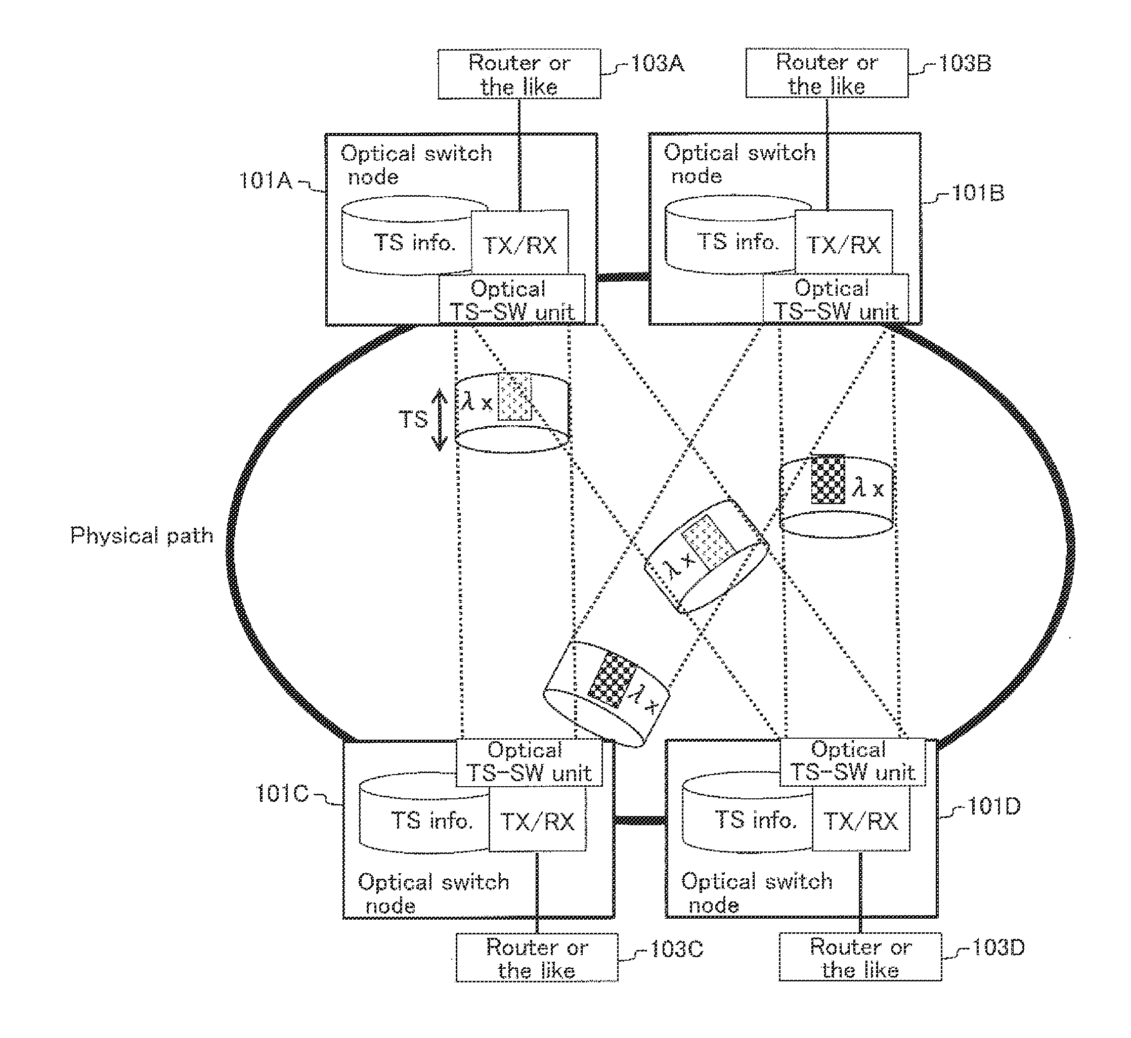
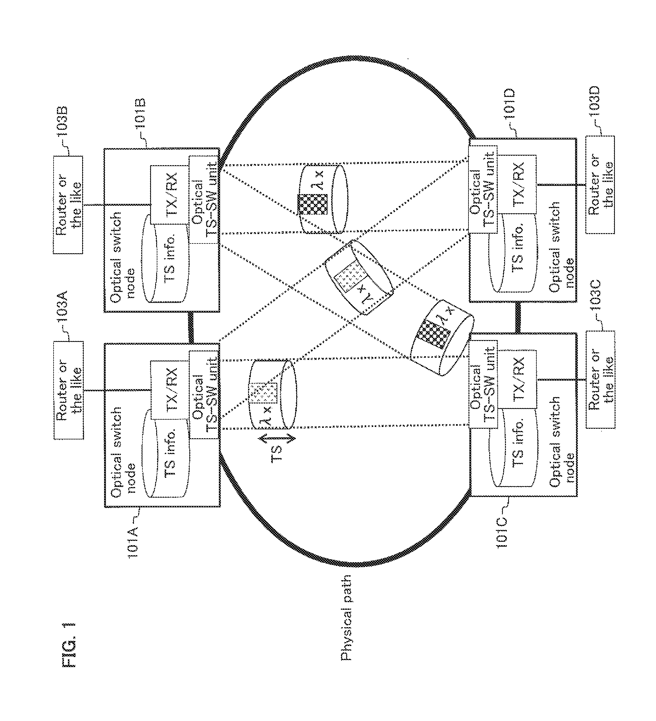
[0246]In the optical network system according to the first embodiment, when the master node transmits a trigger to each of nodes, time slots (TSs) of the nodes are synchronized. The master node then sets a TS length or a TS period at one over the integers. This makes it possible to match a timing at which the trigger is terminated at the master node after one round of a ring, and a timing at which another trigger is outputted, thus allowing periodic data transmission and receipt to be realized in the ring network.

[0247]Next is described a configuration of the optical switch node according to this embodiment.

[0248]FIG. 3 is a block diagram illustrating an example of a configuration of an optical switch node 1 according to this embodiment. FIG. 4 is a diagram schematically illustrating transmission routes of a control signal and an optical signal in the optical switch node 1 illustrated in FIG. 3. Broken arrows show directions in which the control signal is transmitted, and solid arro...

second embodiment

[0308]A second embodiment is configured such that time slot information is embedded in a trigger and is delivered to a node with the trigger embedded therein.

[0309]FIG. 21 is a block diagram illustrating a configuration example of an optical switch node 1E according to a second embodiment. FIG. 22 is a diagram schematically illustrating transmission routes of a control signal and an optical signal in the optical switch node 1E illustrated in FIG. 21.

[0310]As illustrated in FIG. 21, the optical switch node 1E according to the second embodiment does not include the TS information management unit 10 illustrated in FIG. 3. Meanwhile, in the second embodiment, as illustrated in FIG. 22, the trigger detection unit 21 transfers, upon receipt of a trigger, the TS information embedded in the trigger, to the transmission control unit 23 and the optical SW control unit 22.

[0311]FIG. 23 is a block diagram illustrating a configuration example of a master optical switch node (a master node) 2E ac...

third embodiment

[0323]An optical network system according to a third embodiment is configured such that a time at a node is set at a time shifted by a transmission delay time, by transmitting a time stamp from a master node. Thus, time slots are synchronized at a time common to all nodes, at which data transmission and receipt can be realized.

[0324]Next is described a configuration of an optical switch node according to this embodiment.

[0325]FIG. 26 is a block diagram illustrating a configuration example of an optical switch node 1F according to the third embodiment. FIG. 27 is a diagram schematically illustrating transmission routes of a control signal and an optical signal in the optical switch node 1F illustrated in FIG. 26.

[0326]As illustrated in FIG. 26, the optical switch node 1F includes a TS information management unit 10 that sets TS information; a TS synchronization unit 25; a time counter 70; an optical TS-SW unit 30; and a TS transmit-receive unit 40. The TS synchronization unit 25 incl...


PUM


Abstract

An optical network system includes a master node and a plurality of optical switch nodes, allowing the number of nodes without depending on the number of wavelengths. The master node is configured to: divide a wavelength path having an arbitrary wavelength into time slots each having a predetermined time period; and allocate the time slots to each of the optical switch nodes. Each of the optical switch nodes is configured to: synchronize the time slots based on information delivered from the master node; and thereby transmit or receive a data or performs route switching.

Description

TECHNICAL FIELD[0001]The present invention relates to an optical network system, an optical switch node, a master node, and a node.BACKGROUND ART[0002]An optical network system including an OADM (optical add / drop multiplexer) has been known as an optical switch node. An ROADM (Reconfigurable Optical Add / Drop Multiplexer), a type of the OADM, is disclosed in a non-patent document of “HAGIMOTO Kazuo, and two others, “Introduction to Optical Network Becoming More Familiar (15)> (which will be referred to as Non-Patent Document 1 hereinafter). The OADM as its basic configuration is described briefly below.[0003]FIG. 146 is a block diagram illustrating an example of a configuration of a conventional OADM. As illustrated in FIG. 146, the OADM includes an optical SW (which may be used as an abbreviation of a switch hereinafter) setting unit 501, an optical SW unit 502, a demultiplexing unit 503, a multiplexing unit 504, and transmit-receive units 505-1 to 505-N.[0004]FIG. 147 is a diagr...

Claims


Application Information

Patent Timeline
Patent Type & Authority Applications(United States)
IPC IPC(8): H04Q11/00H04J14/02H04J14/08
CPCH04Q11/0005H04J14/08H04Q2011/0086H04Q2011/0045H04Q2011/0033H04J14/0212H04J3/065H04J3/085H04J14/0257H04J14/0267H04J14/0283H04J14/0284H04J14/0286H04Q2213/1301H04J3/0655H04Q2011/005
Inventor HATTORI, KYOTAKIMISHIMA, NAOKINAKAGAWA, MASAHIROKATAYAMA, MASARUMISAWA, AKIRA
Owner NIPPON TELEGRAPH & TELEPHONE CORP
Why Eureka
Try Eureka