Artery visualization device and artery imaging device

a visualization device and imaging device technology, applied in the field of artery visualization devices and imaging devices, can solve the problems of complex manipulation procedures accompanied by scanning a probe, relatively expensive ultrasonic diagnostic equipment, etc., and achieve the effect of efficient inciden

Active Publication Date: 2015-05-14
NAT UNIV CORP KOCHI UNIV
View PDF7 Cites 27 Cited by
  • Summary
  • Abstract
  • Description
  • Claims
  • Application Information

AI Technical Summary

Benefits of technology

[0018]In the artery visualization device according to the present invention, the near-infrared light is incident from the back-side skin surface at the visualization site where the to-be-punctured artery is running, the absorption image of the near-infrared light absorbed by the artery is formed in the imaging unit which captures an image from the side of the back-side skin surface at the visualization site. Since the near-infrared light is incident on the back-side skin surface, the reflection of the near-infrared light does not occur on the surface of the front-side skin surface. Since the light guiding part which encapsulates the light source and is pressed against the back-side skin surface is formed with a material transmitting the near-infrared light and suppressing the reflection of the near-infrared light on the surface of the back-side skin surface, it is possible to allow the near-infrared light to be efficiently incident on the back-side skin surface at the visualization site. By pressing the light guiding part against the back-side skin surface, a capillary network of the skin is collapsed, so that the absorption of the near-infrared light in the skin portion on which the near-infrared light is inc dent is suppressed. As a result, it is possible to very appropriately visualize the to-be-punctured artery.
[0019]According to an artery imaging device, an artery visualization device capable of very appropriately visualizing the to-be-punctured artery may be configured by connecting to an existing display unit, so that the artery imaging device has advantages in terms of costs.

Problems solved by technology

However, manipulation procedures accompanied with scanning a probe are complicated, and the ultrasonic diagnostic equipment is relatively expensive From such a clinical background, a technique of visualizing various arteries with a simple configuration and a relatively low cost, particularly, a technique of visualizing a radical artery has been eagerly waited for.

Method used


Image

  • Artery visualization device and artery imaging device
  • Artery visualization device and artery imaging device
  • Artery visualization device and artery imaging device

Examples


first embodiment

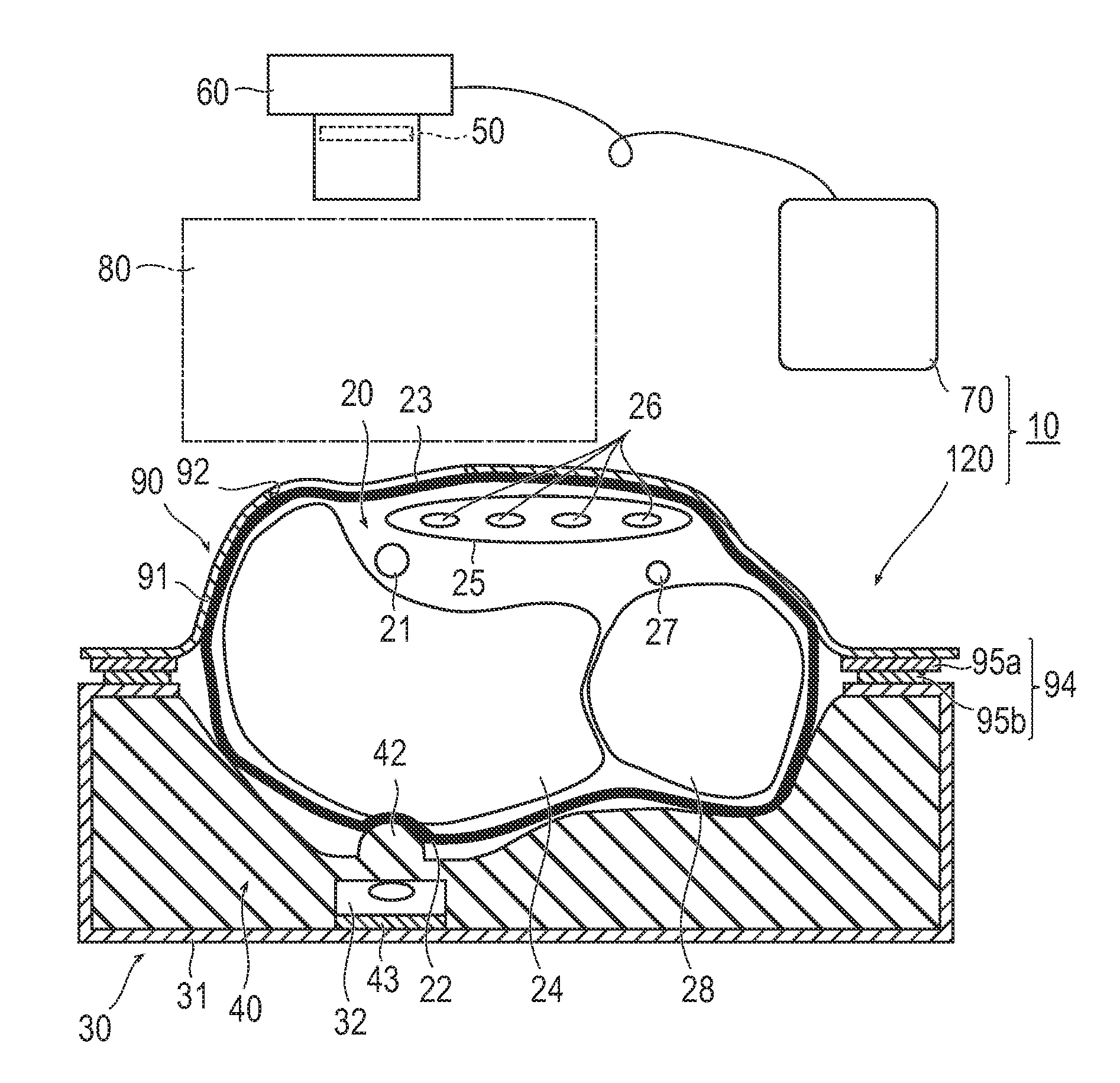
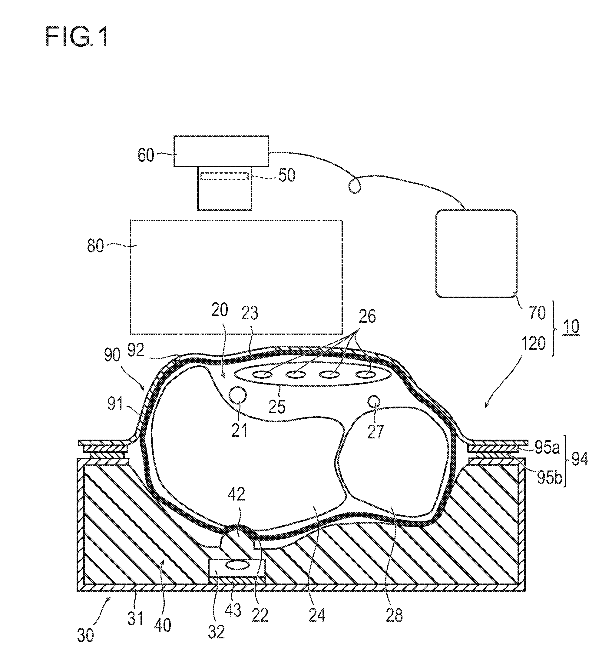
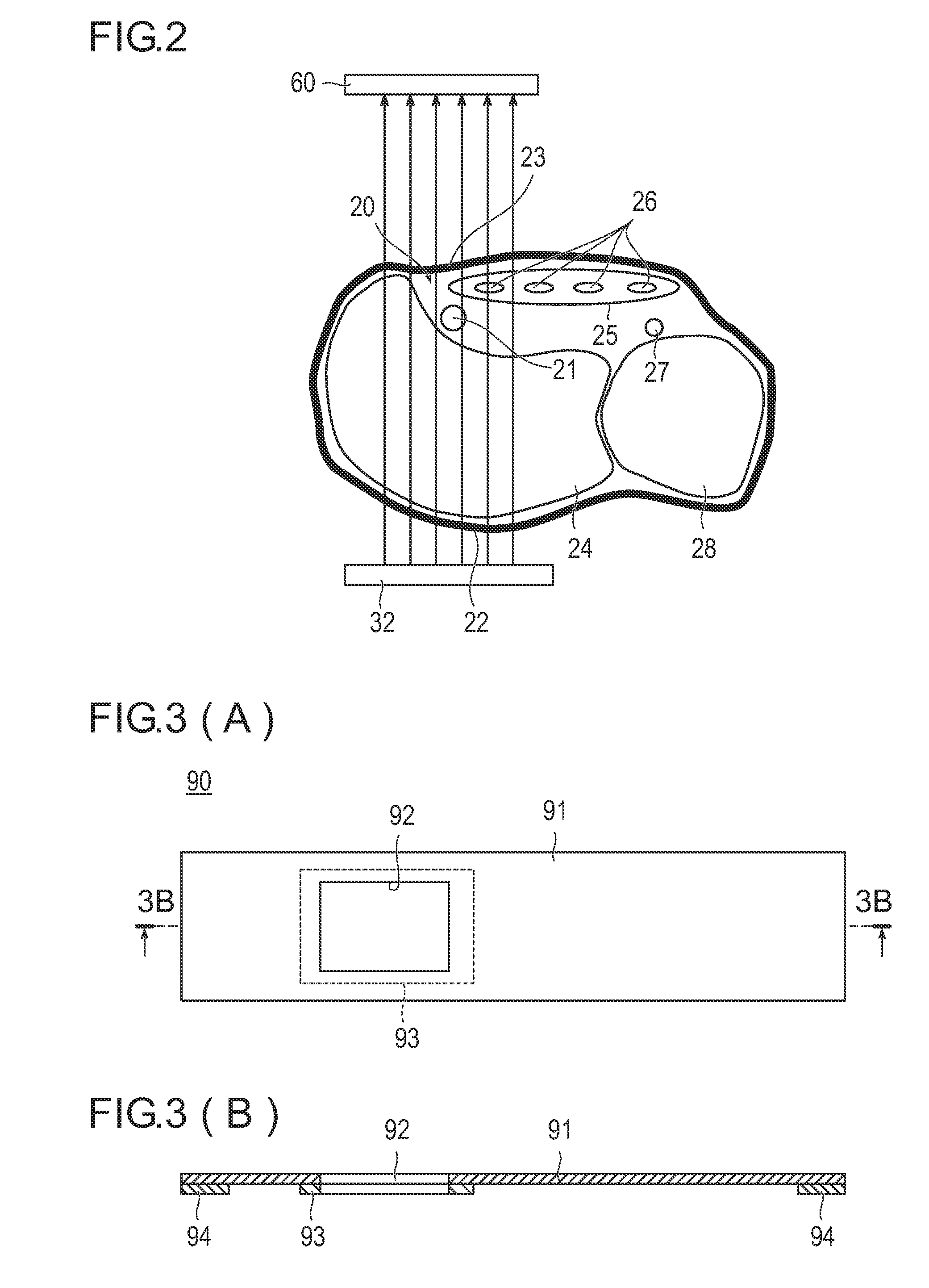
[0034]FIG. 1 is a cross-sectional diagram illustrating an artery visualization device 10 according to a first embodiment, and FIG. 2 is a schematic cross-sectional diagram illustrating a manner of incidence of near-infrared light into a living body. In addition, FIG. 3(A) is front diagram illustrating development of a light shielding member 90 illustrated in FIG. 1, and FIG. 3(B) is a cross-sectional diagram taken along line 3B-3B of FIG. 3(A).

[0035]As described in brief with reference to FIG. 1, the artery visualization device 10 according to the first embodiment is configured to include an irradiation unit 30 which includes a light source 32 emitting near-infrared light and irradiates the near-infrared light emitted from the light source 32 toward a back-side skin surface 22 at a visualization site 20 where a to-be-punctured artery 21 is running, a light guiding part 40 which encapsulates the light source 32 and is pressed against the back-side skin surface 22 and which is formed ...

second embodiment

[0068]FIG. 4 is a cross-sectional diagram illustrating an artery visualization device 11 according to a second embodiment. The same members as those of the first embodiment are denoted by the same reference numerals, and some of the description thereof is omitted.

[0069]Similarly to the first embodiment, the artery visualization device 11 according to the second embodiment is configured to include an irradiation unit 30 which irradiates near-infrared emitted from a light source 32 toward a back-side skin surface 22 at a visualization site 20, a light guiding part 40 which encapsulats the light source 32 and is pressed against the back-side skin surface 22, an optical filter 50, a camera 60, a monitor 70, a work space 80, and a light shielding member 90. However, the second embodiment is different from the first embodiment in that a pressure regulating unit 100 which is capable of regulating a pressure of pressing the light guiding part 40 against the back-side skin surface 22 is furt...

experimental example

[0076]A result of an experiment of visualizing the radial artery 21 by using the artery visualization device 11 illustrated in FIG. 4 will be described.

[0077]As the light source 32 of the irradiation unit 30, one LED (VSMY7850X1 produced by Vishay) having an emission center wavelength of 850 nm was used. A current of 1.75 volts and 720 mA was flowed into the LED. As a material of the light guiding part 40, a liquid silicon rubber (Shin-Etsu Silicone one-component RTV rubber “KE-441” produced by Shin-Etsu Chemical Co., Ltd.) was used. The refractive index of the liquid silicon rubber used is 1.4. The optical filter 50 which blocks components having a wavelength shorter than 840 nm was inserted between the imaging element and the lens of the camera 60. By regulating the air pressure of the balloon by using the pressure regulating unit 100, the pressure of pressing the pressing portion 42 of the light guiding part 40 against the back-side skin surface 22 was regulated to be 40 mmHg. Th...


PUM


Abstract

[Problem] To provide an artery visualization device capable of very appropriately visualizing a to-be-punctured artery and an artery imaging device used for the artery visualization device.[Solution] An artery visualization device (10) includes en irradiation unit (30) which irradiates the near-infrared light emitted from a light source (32) toward a back-side skin surface (22) at a visualization site (20) where a to-be-punctured artery (21) is running, a ht guiding part (40) which encapsulates the light source and is pressed against the back-side skin surface and which is formed with a material of transmitting the near-infrared light emitted from the light, source and suppressing reflection of the near-infrared light on the surface of the back-side skin surface, an optical filter (50) which blocks visible light and transmits the near-infrared light passing through a front-side skin surface (23) at the visualization site, a camera (60) (an imaging unit) which receives the near-infrared light passing through the optical filter to capture an image of the visualization site (20), and a monitor (70) (a display unit) which displays the image captured by the camera.

Description

TECHNICAL FIELD[0001]The present invention relates to an artery visualization device and an artery imaging device.BACKGROUND ART[0002]In examination or treatment using a catheter, for example, in cardiac catheterization examination, an artery is punctured, a guide wire is inserted, and the catheter inserted. The to-be-punctured portion is a radial artery, a brachial artery, a femoral artery, or the like. With respect to the radial artery among these arteries, it is easy to secure rest of hemostasis after examination, and since actions of a patient do not need to be restrained, the radial artery is suitable as a to-be-punctured portion.[0003]On the other hand, a high technique is required for the puncture of the radial artery. In general, the puncture of the radial artery is performed while estimating running of the radial artery by palpation. In the case where the puncture is difficult, the puncture may be sometimes performed by using ultrasonic diagnostic equipment. However, manipu...

Claims


Application Information

Patent Timeline
Patent Type & Authority Applications(United States)
IPC IPC(8): A61B5/00A61B19/00
CPCA61B5/489A61B5/0075A61B5/702A61B2019/202A61B5/6843A61B19/201A61B5/742A61B5/0077A61B5/0086A61B5/6824A61B5/6831A61B2562/185A61M5/427A61B90/11A61B90/13
Inventor SATO, TAKAYUKIIKE, TATSUMI
Owner NAT UNIV CORP KOCHI UNIV
Why Eureka
Try Eureka