System and method of controlling a two-shaft gas turbine

Active Publication Date: 2015-05-21
MITSUBISHI POWER LTD
View PDF34 Cites 18 Cited by
  • Summary
  • Abstract
  • Description
  • Claims
  • Application Information

AI Technical Summary

Benefits of technology

[0013]The present invention controls the amount of intake air spray and the rotational speed of the high-pressure turbine in accordance with the aperture of the inlet guide vane in the state where the two-shaft gas turbine is being operated with its compress

Problems solved by technology

If the combustion temperature rises with the angle of the inlet guide vane fixed, the power output of the high-pressure turbine will be greater with respect to the driving force for the compressor, so that the high-pressure turbine side will excessively be rotated.
Moreover, the age-related degradation of the compressor causes dust to adhere to vanes or blades, which leads to lower cascade performance.
Furthermore, the compressor that sprays droplets is such that droplets adhere to the surfaces of vanes or blades; there

Method used


Image

  • System and method of controlling a two-shaft gas turbine
  • System and method of controlling a two-shaft gas turbine
  • System and method of controlling a two-shaft gas turbine

Examples


Example

First Embodiment

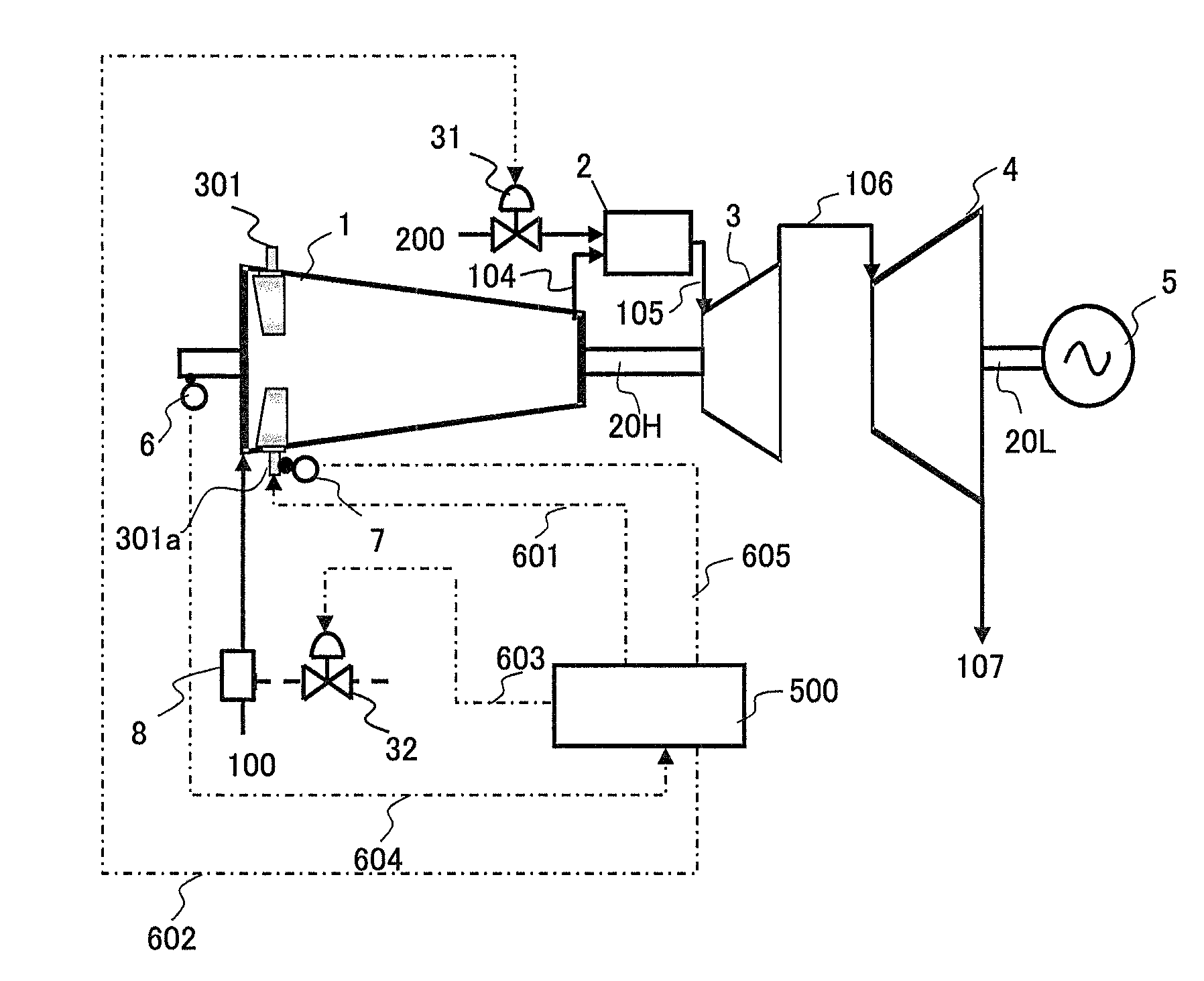
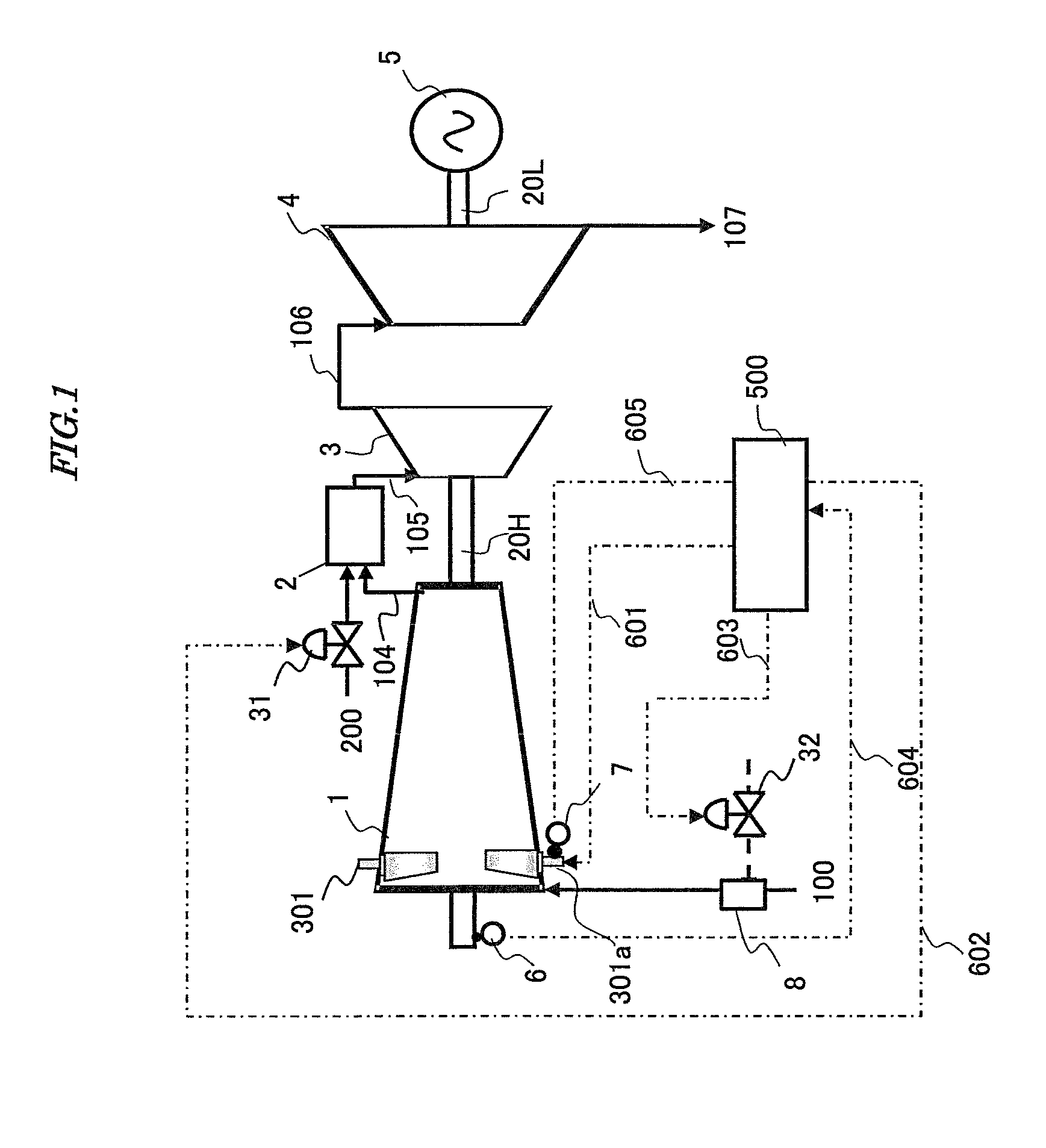
[0022]FIG. 1 is a schematic configuration diagram illustrating a two-shaft gas turbine system according to a first embodiment of a two-shaft gas turbine control system and method of the present invention.

[0023]The two-shaft gas turbine system includes a compressor 1 for compressing air 100 sucked from the atmosphere to generate high-pressure air 104; a combustor 2 for mixing the high-pressure air 104 with fuel 200 for sake of combustion to generate high-temperature combustion gas 105; a high-pressure turbine 3 rotatably driven by the high-temperature combustion gas 105 thus generated; a low-pressure turbine 4 rotatably driven by expanded combustion gas 106 expanded in the high-pressure turbine 3 and introduced thereinto; and a generator 5 which is a load of the low-pressure turbine 4. The compressor 1 and the high pressure turbine 3 are mechanically connected by a first rotating shaft 20H. The low-pressure turbine 4 and the generator 5 are mechanically connected by u...

Example

Second Embodiment

[0061]A second embodiment of a two-shaft gas turbine control system and method according to the present invention will hereinafter be described with reference to the drawings. FIG. 6 is a schematic configuration diagram illustrating a two-shaft gas turbine system according to the second embodiment of the two-shaft gas turbine control system and method of the present invention. In FIG. 6, portions attached with the same reference numerals as those in FIGS. 1 to 5 are like portions and their detailed explanation are thus omitted.

[0062]The second embodiment of the two-shaft gas turbine control system and method according to the present invention illustrated in FIG. 6 is configured to have almost the same devices as those of the first embodiment. However, the second embodiment is different from the first embodiment in the following configuration. The present embodiment includes a first thermometer 9a for detecting the intake air temperature of the compressor 1, a first ...

Example

Third Embodiment

[0066]A third embodiment of a two-shaft gas turbine control system and method according to the present invention will hereinafter be described with reference to the drawings. FIG. 7 is a schematic configuration diagram illustrating a two-shaft gas turbine system according to the third embodiment of the two-shaft gas turbine control system and method of the present invention. In FIG. 7, portions attached with the same reference numerals as those in FIGS. 1 to 4 are like portions and their detailed explanations are thus omitted.

[0067]The third embodiment of the two-shaft gas turbine control system and method according to the present invention illustrated in FIG. 7 is configured to have almost the same devices as those of the first embodiment. However, the third embodiment is different from the first embodiment in the following configuration. In the present embodiment, a blade tip clearance sensor 10 for measuring a tip clearance is provided at an intermediate stage of ...


PUM


Abstract

A two-shaft gas turbine control system and method are provided that can enhance the efficiency and reliability thereof by controlling the amount of intake air spray and the rotational speed of a high-pressure turbine in accordance with the aperture of an inlet guide vane in a state where a two-shaft gas turbine is being operated with the efficiency of its compressor reduced.
The control system includes a droplet spray device for spraying droplets to intake air for the compressor and a controller. The controller includes a fuel control section for adjusting a flow rate of the fuel to be supplied to the combustor, a spray flow rate control section for adjusting a flow rate of spray water to be supplied to the droplet spray device, an inlet guide vane aperture control section for adjusting the aperture of the inlet guide vane, and an efficiency improvement control section for outputting a command signal for bringing a balance between driving force for the compressor and power output of the high-pressure turbine to the fuel control section, the spray flow rate control section and the inlet guide aperture control section. In response to the commands from the improvement control section, the controller reduces the rotational speed of the high-pressure turbine and controls the inlet guide vane so as to be more open, thereby appropriately controlling the flow rate of the spray water.

Description

BACKGROUND OF THE INVENTION[0001]1. Field of the Invention[0002]The present invention relates to a system for and a method of controlling a two-shaft gas turbine.[0003]2. Description of the Related Art[0004]A two-shaft gas turbine is configured such that a high-pressure turbine driving a compressor and a low-pressure turbine driving a generator or a pump respectively have different shafts. This two-shaft gas turbine can rotate the compressor and the high-pressure turbine at high a speed even when a driven machine such as a pump and a screw compressor is rotated at a low speed. Therefore, the torque of the low-pressure turbine rotated at a low speed can be increased. For this reason, the two-shaft gas turbine is used to drive a machine such as a pump and a screw compressor. However, the two-shaft gas turbine also can be used such that the low-pressure turbine is used to drive the generator for electric power generation. When the two-shaft gas turbine is used without a speed reducer, ...

Claims


Application Information

Patent Timeline
IPC IPC(8): F02C3/107F02C7/36F02C9/56
CPCF02C3/107F02C7/36F02C9/56F02C3/10F02C7/1435F02C9/54F05D2270/023F05D2270/16F05D2270/304Y02T50/60
Inventor TAKAHASHI, YASUOTAKEDA, TAKUYA
Owner MITSUBISHI POWER LTD
Why Eureka
Try Eureka