Image Acquisition Method and Transmission Electron Microscope

a technology of image acquisition and transmission electron microscope, which is applied in the direction of instruments, mass spectrometers, beam deviation/focusing by electric/magnetic means, etc., can solve the problems of inability to obtain information about objects ranging in size and varying in size, and the optical system of a conventional transmission electron microscope cannot transmit information about low spatial frequency and information about high spatial frequency at the same time, so as to achieve suppressed attenuation of contrast transfer function due to spatial envelope function

Inactive Publication Date: 2015-05-21
JEOL LTD
View PDF2 Cites 5 Cited by
  • Summary
  • Abstract
  • Description
  • Claims
  • Application Information

AI Technical Summary

Benefits of technology

[0015]In this image acquisition method, even if the amount of defocus is increased, attenuation of the contrast transfer function due to a spatial envelope function can be suppressed. Therefore, if the amount of defocus is increased, information about high spatial frequencies is not impaired. Consequently, information about low to high spatial frequencies in a wide frequency range can be obtained.
[0017]In this image acquisition method, the spherical aberration coefficient of the imaging system can be set easily. Therefore, the contrast transfer function can be easily varied such that the imaging system becomes adapted to the size of a structure or object under observation.
[0019]In this image acquisition method, the chromatic aberration coefficient of the imaging system can be set easily. Accordingly, the contrast transfer function can be easily varied such that the imaging system becomes adapted to the size of the structure or object under observation.
[0021]According to this image acquisition method, even if the amount of defocus is increased, attenuation of the contrast transfer function due to the spatial envelope function can be suppressed. Accordingly, if the amount of defocus is increased, information about high spatial frequencies is not impaired. Information about low to high spatial frequencies in a wide frequency range can be obtained.
[0023]In this transmission electron microscope, if the amount of defocus is increased, attenuation of the contrast transfer function due to the spatial envelope function can be suppressed. Accordingly, if the amount of defocus is increased, information about high spatial frequencies is not impaired. An optical system capable of transferring information about low to high spatial frequencies in a wide frequency range can be accomplished.
[0025]In this transmission electron microscope, even if the amount of defocus is increased, attenuation of the contrast transfer function due to a spatial envelope function can be suppressed. Accordingly, even if the amount of defocus is increased, information about high spatial frequencies is not impaired. An optical system capable of transferring information about low to high spatial frequencies in a wide frequency range can be accomplished.

Problems solved by technology

However, the optical system of a conventional transmission electron microscope cannot transmit information about low spatial frequencies and information about high spatial frequencies at the same time.
It has been impossible to obtain information about objects ranging widely in size for the reason described below.
However, as the amount of defocus is increased, information about high spatial frequencies is impaired due to attenuation of the spatial envelope function as shown in FIG. 11.
In this way, with the conventional optical system of a transmission electron microscope, it has been impossible to obtain information about low spatial frequencies and information about high spatial frequencies at the same time.

Method used


Image

  • Image Acquisition Method and Transmission Electron Microscope
  • Image Acquisition Method and Transmission Electron Microscope
  • Image Acquisition Method and Transmission Electron Microscope

Examples


first embodiment

1. First Embodiment

1.1. Transmission Electron Microscope

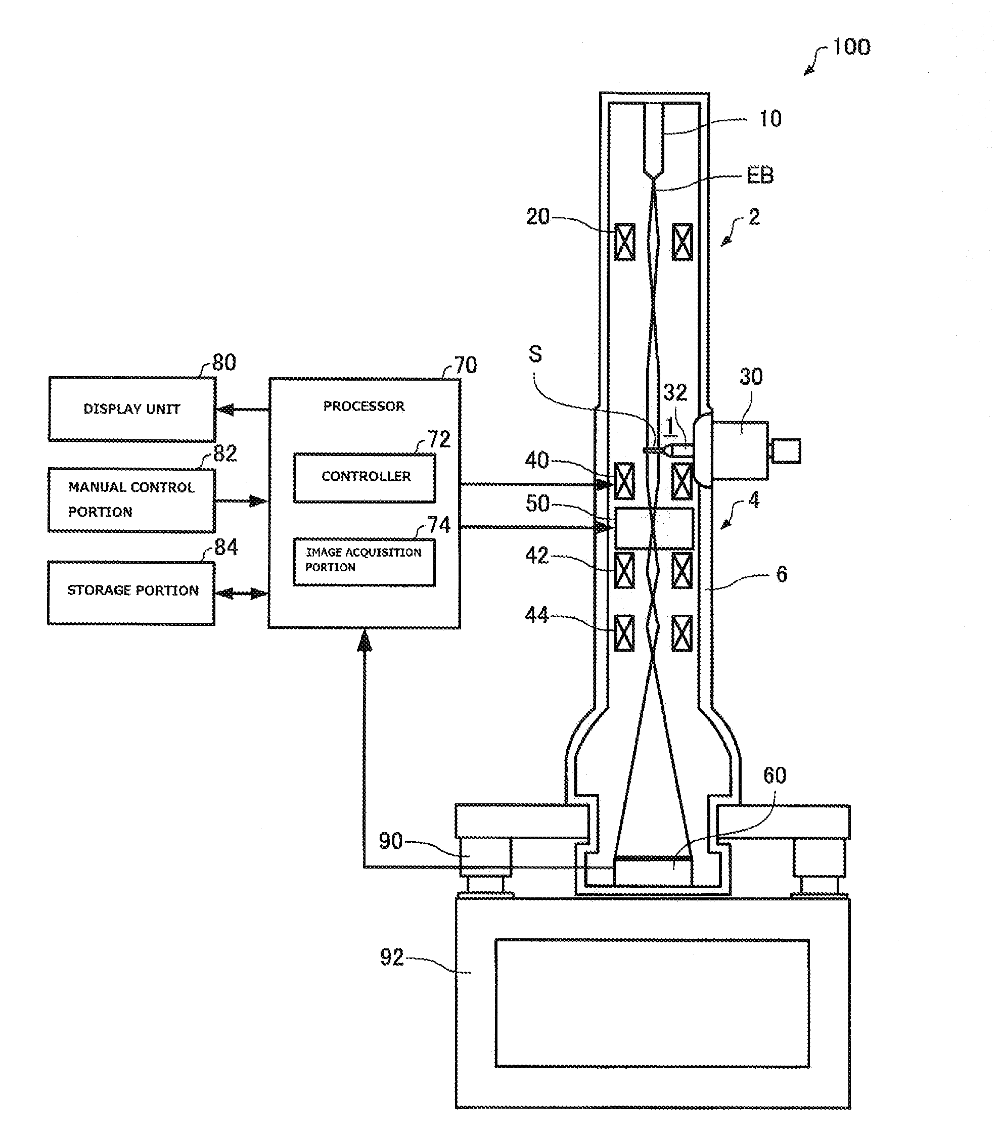
[0038]A transmission electron microscope associated with a first embodiment of the present invention is first described by referring to FIG. 1, which shows the configuration of the transmission electron microscope, 100.

[0039]As shown in FIG. 1, the transmission electron microscope 100 is configured including an electron beam source 10, an illumination system 2 (having an illumination lens system), a sample stage 30, an imaging system 4 (having an imaging lens system), a spherical aberration corrector 50, an image pickup device 60, a processor 70, a display unit 80, a manual control portion 82, and a storage portion 84. In the condition shown in FIG. 1, a sample holder 32 is inserted in a sample chamber 1.

[0040]The transmission electron microscope 100 including the illumination system 2 and the imaging system 4 further includes an optical system accommodated within an optical column 6. The interior of the optical column 6 is pum...

second embodiment

2. Second Embodiment

2.1. Transmission Electron Microscope

[0100]A transmission electron microscope associated with a second embodiment of the present invention is next described by referring to FIG. 8, which shows the configuration of this transmission electron microscope, 200. Those components of the transmission electron microscope 200 which are similar in function with their respective counterparts of the above-described transmission electron microscope 100 associated with the first embodiment are indicated by the same reference numerals as in the above cited figures and a description thereof is omitted.

[0101]As shown in FIG. 1, the above-described transmission electron microscope 100 has the spherical aberration corrector 50. The imaging system 4 having a large spherical aberration coefficient Cs and a small chromatic aberration coefficient Cc is built by setting the spherical aberration coefficient Cs of the imaging system 4 by the use of the spherical aberration corrector 50. A...


PUM


Abstract

An image acquisition method and system for use in transmission electron microscopy and capable of providing information about a wide range of frequency range. The method is initiated with setting at least one of the spherical aberration coefficient and chromatic aberration coefficient of the imaging system of the microscope to suppress attenuation of a contrast transfer function due to an envelope function. Then, an image is obtained by the imaging system placed in defocus conditions.

Description

BACKGROUND OF THE INVENTION[0001]1. Field of the Invention[0002]The present invention relates to an image acquisition method and transmission electron microscope.[0003]2. Description of Related Art[0004]Generally, a transmission electron microscope (TEM) is required to have an imaging system that has a small spherical aberration coefficient Cs for providing improved point resolution and a small chromatic aberration coefficient Cc for providing improved lattice resolution (see, for example, JP-A-11-135047).[0005]A point resolution of an objective lens is defined by the first zero of a contrast transfer function (CTF) at the Scherzer focus. As the spherical aberration coefficient Cs decreases, the point resolution is improved. The first zero indicates a wave number at which the phase contrast transfer function at the Scherzer focus first crosses the axis of phase zero. The reciprocal of this wave number is the point resolution.[0006]A contrast transfer function at the Scherzer focus i...

Claims


Application Information

Patent Timeline
Patent Type & Authority Applications(United States)
IPC IPC(8): H01J37/21H01J37/22H01J37/26
CPCH01J37/21H01J37/26H01J37/226H01J2237/0492H01J2237/21H01J2237/2007H01J2237/10H01J2237/2602H01J37/263H01J37/265H01J2237/1534H01J2237/2614
Inventor IIJIMA, HIROFUMI
Owner JEOL LTD
Why Eureka
Try Eureka