
Method for manufacturing a magnetic tape head using an ink mask formed by printing

a printing and ink mask technology, applied in the field of magnetic data recording, can solve the problems of increasing the loss of the wallace spacing, and increasing the spacing between the magnetically active portion of the sensor and the magnetic coating on the tape, so as to protect the tape from damage and corrosion without increasing the magnetic spacing

Inactive Publication Date: 2015-05-21
WESTERN DIGITAL TECH INC
View PDF9 Cites 21 Cited by
  • Summary
  • Abstract
  • Description
  • Claims
  • Application Information

AI Technical Summary

Benefits of technology

The patent describes a method for protecting a magnetic transducer on a tape from wear and corrosion without increasing the magnetic spacing. This is achieved by creating a cavity in the tape surface where the protective coating is aligned with the cavity to cover only the transducer. The tape surface is then printed with an ink mask that is easily removable, followed by etching and deposition of the protective coating. This method provides optimal surface tension for printing while protecting the transducer from damage.

Problems solved by technology

However, the development of small footprint, higher performance tape drive systems has created various problems in the design of a tape head assembly for use in such systems.
The Wallace spacing is, among other factors, due to asperities on the tape and to erosion of the sensor due to wear.
Build up of non-magnetic material between the sensor and the tape magnetic coating can also cause Wallace spacing.
Corrosion or oxidation initiated at the TBS of the sensor or the protective poles surrounding the sensor can also lead to increased Wallace spacing losses.
Corrosion or oxidation of the sensor at the TBS can result in surface oxidation of the sensor metals which results in an increase in the spacing between the magnetically active portion of the sensor and the magnetic coating on the tape.
High level corrosion can completely destroy the magnetic response of the sensor.
However, such materials are in contact with the tape, and tend to wear away, thereby leaving the sensor unprotected.
The available methods of depositing the hard protective coatings require large expensive tools which preclude the reapplication of a hard coating once it has been worn off.
Furthermore, such recession results in Wallace spacing signal losses, which are exacerbated at higher data density.
This leads to an increase in spacing between the magnetic transducer and the tape, resulting in increased Wallace spacing and decreased performance.

Method used


Image

  • Method for manufacturing a magnetic tape head using an ink mask formed by printing
  • Method for manufacturing a magnetic tape head using an ink mask formed by printing
  • Method for manufacturing a magnetic tape head using an ink mask formed by printing

Examples


Embodiment Construction

[0019]The following description is of the best embodiments presently contemplated for carrying out this invention. This description is made for the purpose of illustrating the general principles of this invention and is not meant to limit the inventive concepts claimed herein.

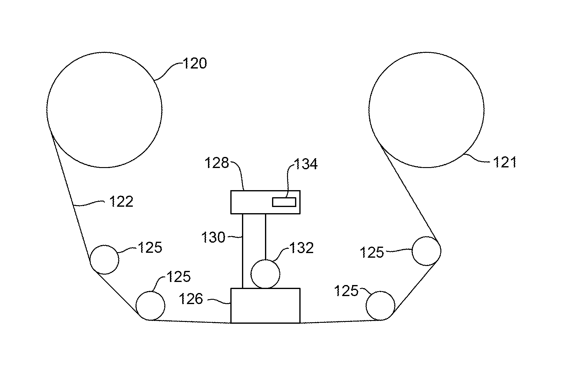
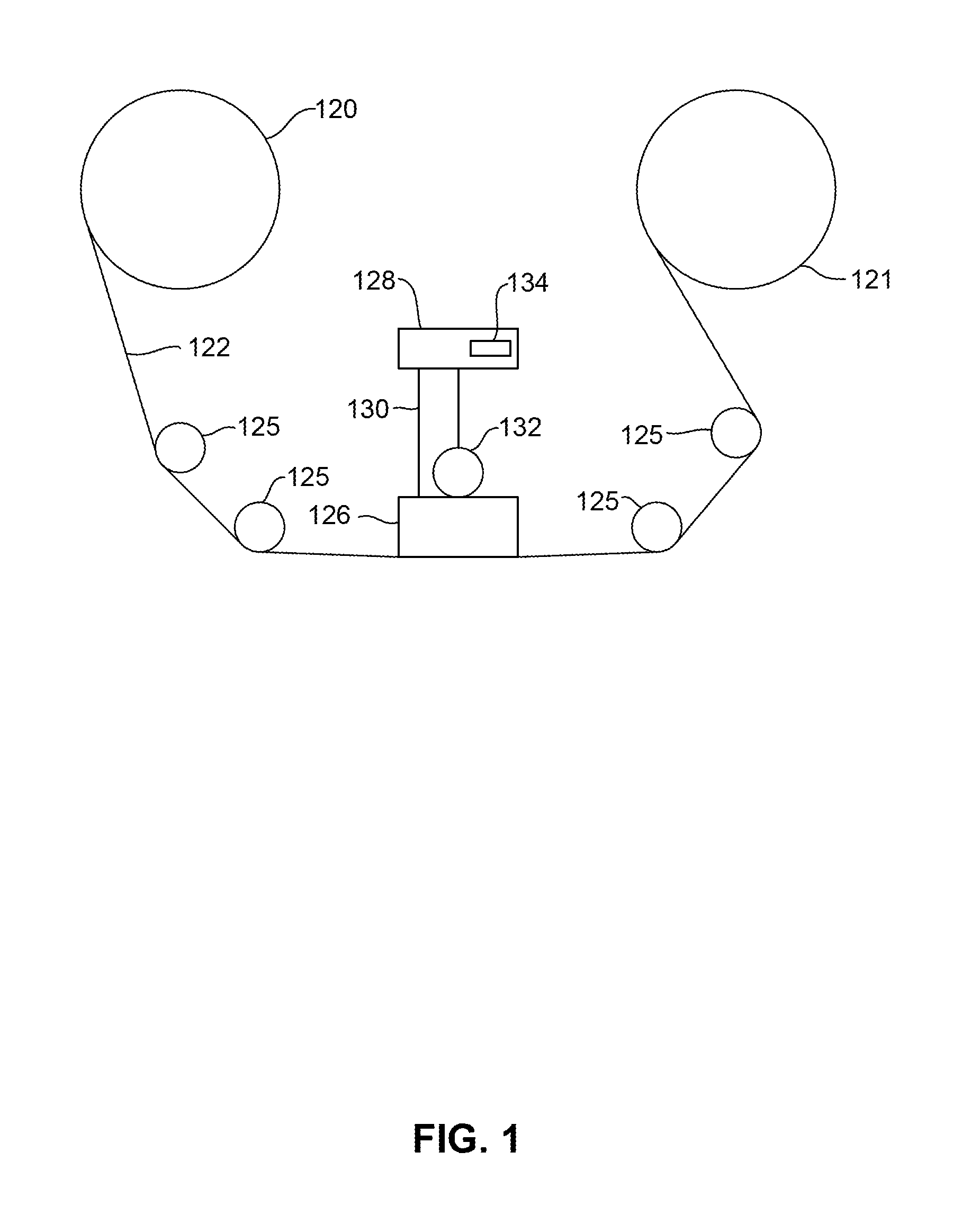
[0020]FIG. 1 is a schematic illustration of a tape drive 100 of a tape-based storage system. While one specific implementation of a tape drive is shown in FIG. 1, it should be noted that the embodiments describe herein may be implemented in the context of any type of tape drive system.

[0021]As shown, a tape supply cartridge 120 and a take-up reel 121 are provided to support a tape 122. One or more of the reels 121 may form a part of a removable cartridge and are not necessarily part of the system 100. The tape drive, such as that illustrated in FIG. 1, may further include drive motor(s) (not shown) to drive the tape supply cartridge 120 and the take-up reel 121 to move the tape 122 over a tape head 126 of any t...


PUM


Abstract

A method for forming a protective overcoat onto a tape bearing surface of a tape head used for magnetic tape recording. In order to ensure optimal surface tension and liftoff properties of the ink mask, the tape bearing surface is treated with a first application of ethanol, followed by an application of polydimethylsiloxane, followed by a second application of ethanol. After this treatment an ink mask can be printed onto the tape bearing surface so as to form a mask having an opening over the location of the magnetic transducer. An etching can then be performed followed by the deposition of a protective coating such as alumina.

Description

FIELD OF THE INVENTION[0001]The present invention relates to magnetic data recording and more particularly to a method for manufacturing a magnetic tape head using ink printing to pattern an overcoat with high resolution.BACKGROUND OF THE INVENTION[0002]In magnetic storage systems, data is read from and written onto magnetic recording media utilizing magnetic transducers. Data is written on the magnetic recording media by moving a magnetic recording transducer to a position over the media where the data is to be stored. The magnetic recording transducer then generates a magnetic field, which encodes the data into the magnetic media. Data is read from the media by similarly positioning the magnetic read transducer and then sensing the magnetic field of the magnetic media. Read and write operations may be independently synchronized with the movement of the media to ensure that the data can be read from and written to the desired location on the media.[0003]An important and continuing ...

Claims


Application Information

Patent Timeline
IPC IPC(8): G11B5/33G11B5/40
CPCG11B5/40G11B5/33G11B5/00826G11B5/3106G11B5/3977
Inventor ADRONG, QUEHWANG, CHERNGYENGUYEN, DUNG T.TORRES MIRELES, EDUARDO
Owner WESTERN DIGITAL TECH INC
Learn More