
Color liquid crystal display panel and manufacturing method thereof

a liquid crystal display panel and liquid crystal technology, applied in the manufacture of electrode systems, electric discharge tubes/lamps, instruments, etc., can solve the problems of display panel extreme strong effect, waste of most of backlighting energy, etc., to reduce the requirement for backlighting brightness, enhance light transmittal, and reduce manufacturing costs

Active Publication Date: 2015-05-28
SHENZHEN CHINA STAR OPTOELECTRONICS TECH CO LTD
View PDF7 Cites 8 Cited by
  • Summary
  • Abstract
  • Description
  • Claims
  • Application Information

AI Technical Summary

Benefits of technology

The present invention provides a color liquid crystal display panel and a manufacturing method that has a simple structure, requires no inclusion of a polarizer, has a simple manufacturing process, low energy consumption, reduces the manufacture cost of the color liquid crystal display panel, reduces the requirement of backlighting brightness, and enhances light transttal and optical efficiency. The efficacy of the invention is achieved through the use of dichroic dye which allows for adjusting light intensity and achieving color displaying without the need for a polarizer. This results in a reduced manufacturing cost, reduced energy consumption, and improved light transmission and optical efficiency of the color liquid crystal display.

Problems solved by technology

It is now a problem to be faced by all industries and businesses to develop and make products that is more energy saving and more environmentally conservative.
However, some components of such a structure of color liquid crystal display panel have extremely strong effects of absorption and filtering of light.
Most of the energy of the backlighting is wasted.

Method used

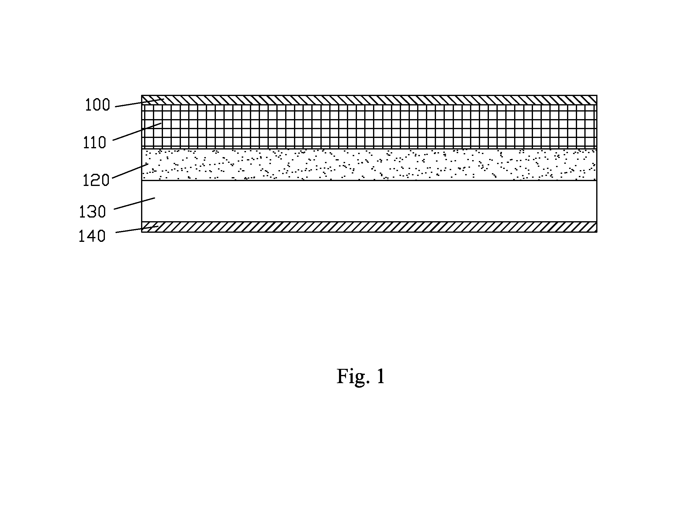

Image

  • Color liquid crystal display panel and manufacturing method thereof
  • Color liquid crystal display panel and manufacturing method thereof
  • Color liquid crystal display panel and manufacturing method thereof

Examples


Embodiment Construction

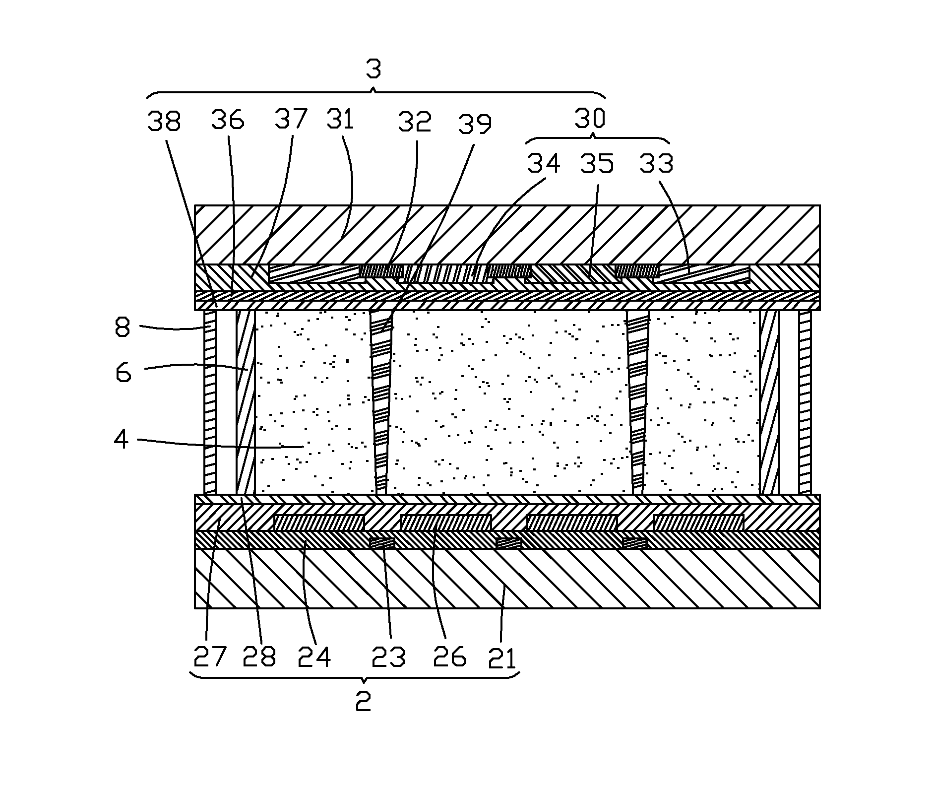
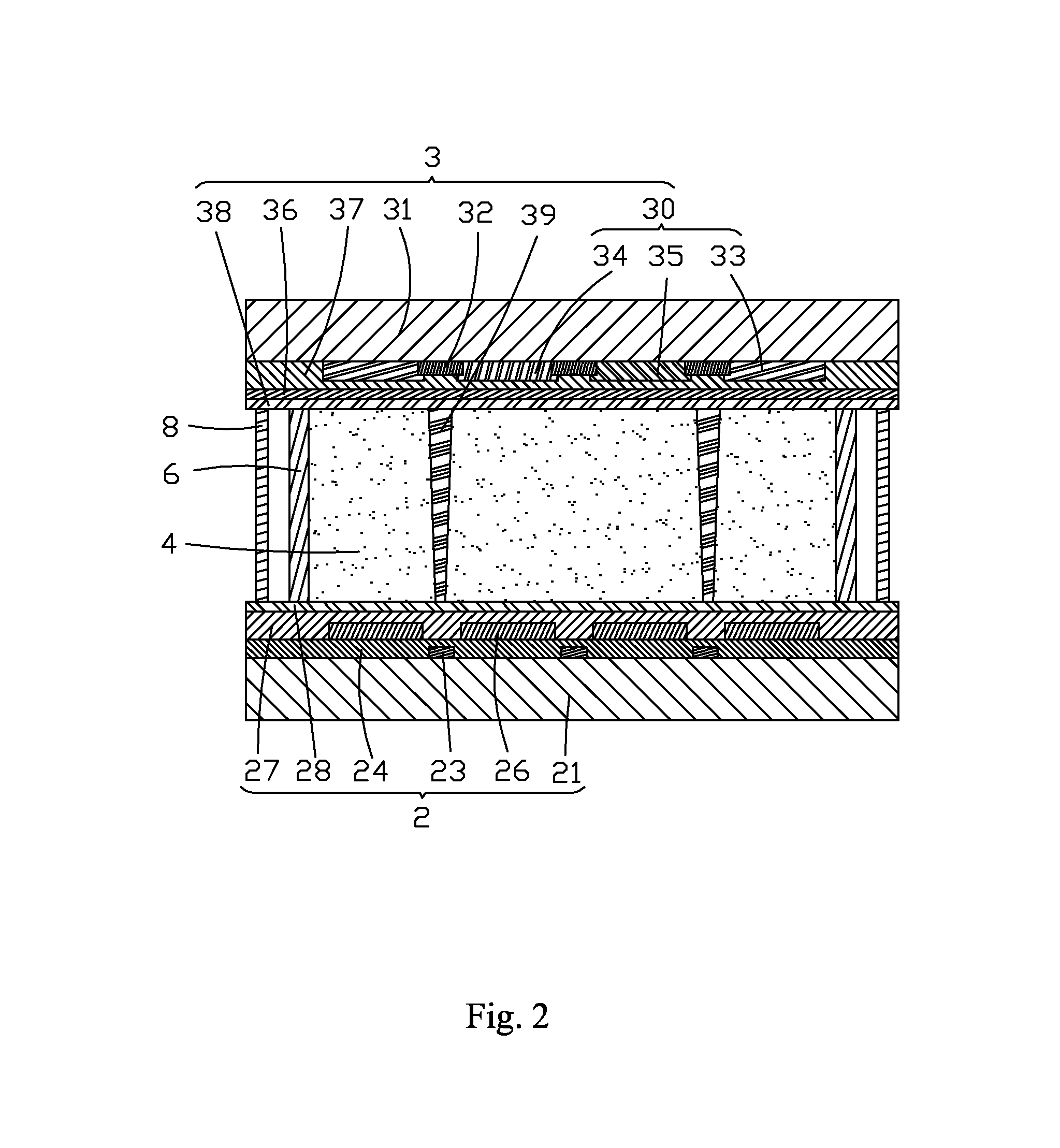
[0043]Referring to FIGS. 2-4, the present invention provides a color liquid crystal display panel, which comprises: a first substrate 2, a second substrate 3 laminated on the first substrate 2, and dye-doped liquid crystal layers 4 hermetically sealed between the first substrate 2 and the second substrate 3.

[0044]As shown in FIGS. 2 and 3, the first substrate 2 is a thin-film transistor array substrate. The first substrate 2 comprises a first transparent substrate 21, a plurality of gate lines 22 formed on the first transparent substrate 21, a plurality of data lines 23 formed on the first transparent substrate 21, an array of thin-film transistors 25 formed on the first transparent substrate 21, an insulation layer 24 formed on the array of thin-film transistors 25, the data lines 23, and the first transparent substrate 21, pixel electrodes 26 formed on the insulation layer 24, a first planarization layer 27 formed on the pixel electrodes 26 and the insulation layer 24, and a first...


PUM


Abstract

The present invention provides a color liquid crystal display panel and a manufacturing method thereof. The color liquid crystal display panel includes: a first substrate (2), a second substrate (3), and dye-doped liquid crystal layers (4) hermetically sealed between the first substrate (2) and the second substrate (3). The dye-doped liquid crystal layers (4) each include a liquid crystal material, a chiral dopant, and at least one dichroic dye. Each of the dichroic dyes absorbs a light of a predetermined wavelength range. The color liquid crystal display panel and the manufacturing method thereof according to the present invention add at least one dichroic dye in a liquid crystal material so as to use selective absorbability of the dichroic dye with respect to visible lights to adjust light intensity and also to achieve color displaying through collaboration of a color filter and the dichroic dye, whereby there is no need to include a conventionally used polarizer so as to reduce the manufacturing cost of the color liquid crystal display panel, also reduce the requirement for backlighting brightness, enhance light transmittal and optical efficiency, and thus lower down energy consumption of the operation of a color liquid crystal display.

Description

BACKGROUND OF THE INVENTION[0001]1. Field of the Invention[0002]The present invention relates to the field of liquid crystal display technology, and in particular to a color liquid crystal display panel and a manufacturing method thereof.[0003]2. The Related Arts[0004]The continuous progress of the modern industry makes the issues of energy shortage and environmental pollution more prominent and these issues of environment and energy are attracting increasing attention of people. It is now a problem to be faced by all industries and businesses to develop and make products that is more energy saving and more environmentally conservative. The liquid crystal displaying industry is similarly facing the same challenge. Thus, it has been a problem to be settled to develop liquid crystal displays that are more energy saving and have increased efficiency.[0005]Liquid crystal displays (LCDs) have a variety of advantages, such as thin device body, low power consumption, and being free of radi...

Claims


Application Information

Patent Timeline
IPC IPC(8): G02F1/1335G02F1/1362G02F1/1368G02F1/1339
CPCG02F1/133514G02F1/1339G02F2001/133357G02F1/1368G02F1/136286G02F1/1362G02F1/13737G02F1/13706
Inventor ZHONG, XINHUI
Owner SHENZHEN CHINA STAR OPTOELECTRONICS TECH CO LTD
Learn More