
Apparatus and method for measuring biologic parameters

a technology of biologic parameters and apparatus, applied in the field of apparatus and method for measuring biologic parameters, can solve the problems of preventing the clinical value of measured biologic parameters, the inability to provide continuous monitoring for a long period of time, and the failure of non-invasive techniques to deliver the clinical usefulness needed, so as to avoid dehydration or overhydration, increase the effect of performance and safety

Active Publication Date: 2015-05-28
BRAIN TUNNELGENIX TECH CORP
View PDF1 Cites 19 Cited by
  • Summary
  • Abstract
  • Description
  • Claims
  • Application Information

AI Technical Summary

Benefits of technology

The invention provides a set of sensing systems and reporting means that can measure various biological, physical, and chemical parameters of the body. This is achieved through a direct and undisturbed connection between the source of function within the body and an external point at the end of a tunnel on the skin, known as a physiologic tunnel. The sensor placed on the skin at the end of the tunnel allows optimal signal acquisition without interfering constituents and sources of error. Additionally, the invention provides support structures that transmit the signals produced at the tunnel to treadmills and other exercise machines to help keep the user hydrated and prevent temperature disturbances.

Problems solved by technology

Interfering constituents and variables can introduce significant source of errors that prevent measured biologic parameters from being of clinical value.
Such techniques have many drawbacks including difficulties in providing continuous monitoring for long periods of time.
Non-invasive techniques also failed to deliver the clinical usefulness needed.
The placement of a sensor on the skin characterized by the presence of interfering constituents do not allow obtaining clinically useful nor accurate signals due to the presence of said interfering constituents and background noise which greatly exceeds the signal related to the physiologic parameter being measured.
Thus measurement of temperature using the skin did not achieve precision nor accuracy because previous techniques used sensors placed on skin characterized by the presence of adipose tissue.
An invasive, artificial, inconvenient, and costly process is currently used to measure internal (core) temperature consisting of inserting a catheter with a temperature sensor in the urinary canal, rectum or esophagus.
But such methodology is not suitable for routine measurement, it is painful, and has potential fatal complications.
Abreu disclosed in U.S. Pat. No. 6,120,460 apparatus and methods for measuring core temperature continuously using a contact lens in the eyelid pocket, but the contact lens is a semi-invasive device which requires prescription by a physician and sometimes it is not easy to place the contact lens in the eye of an infant or even in adults and many people are afraid of touching their eyes.
There are several drawbacks and limitations in the prior art for continuous and / or core measurement of temperature.
To get core temperature nurses invasively place a tube inside the body which can cause infection and costly complications.
Measurement of core temperature on a routine basis in the hospital and / or continuously is very difficult and risky because it requires an invasive procedure with insertion of tubes inside the body or by ingesting a thermometer pill.
The thermometer pill can cause diarrhea, measure temperature of the fluid / food ingested and not body temperature, and have fatal complications if the pill obstructs the pancreas or liver ducts.
Placement of sensors on the skin do not provide clinically useful measurements because of the presence of many interfering constituents including fat tissue.
It is not possible to acquire precise and clinically useful measurements of not only brain temperature, but also metabolic parameters, physical parameters, chemical parameters, and the like by simply placing a sensor on the skin.

Method used


Image

  • Apparatus and method for measuring biologic parameters
  • Apparatus and method for measuring biologic parameters
  • Apparatus and method for measuring biologic parameters

Examples


Embodiment Construction

[0267]In describing a preferred embodiment of the invention illustrated in the drawings, specific terminology will be resorted to for the sake of clarity. However, the invention is not intended to be limited to the specific terms so selected, and it is to be understood that each specific term includes all technical equivalents which operate in a similar manner to accomplish a similar purpose.

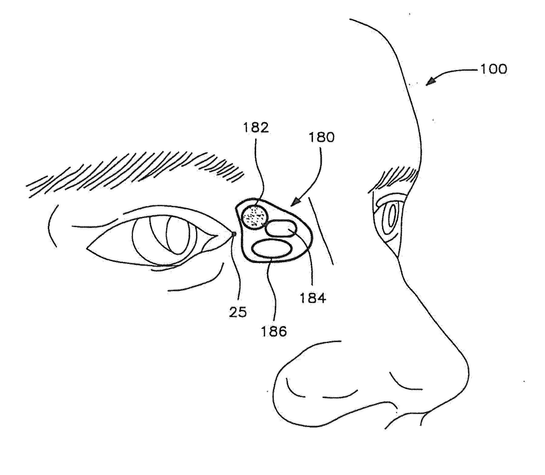
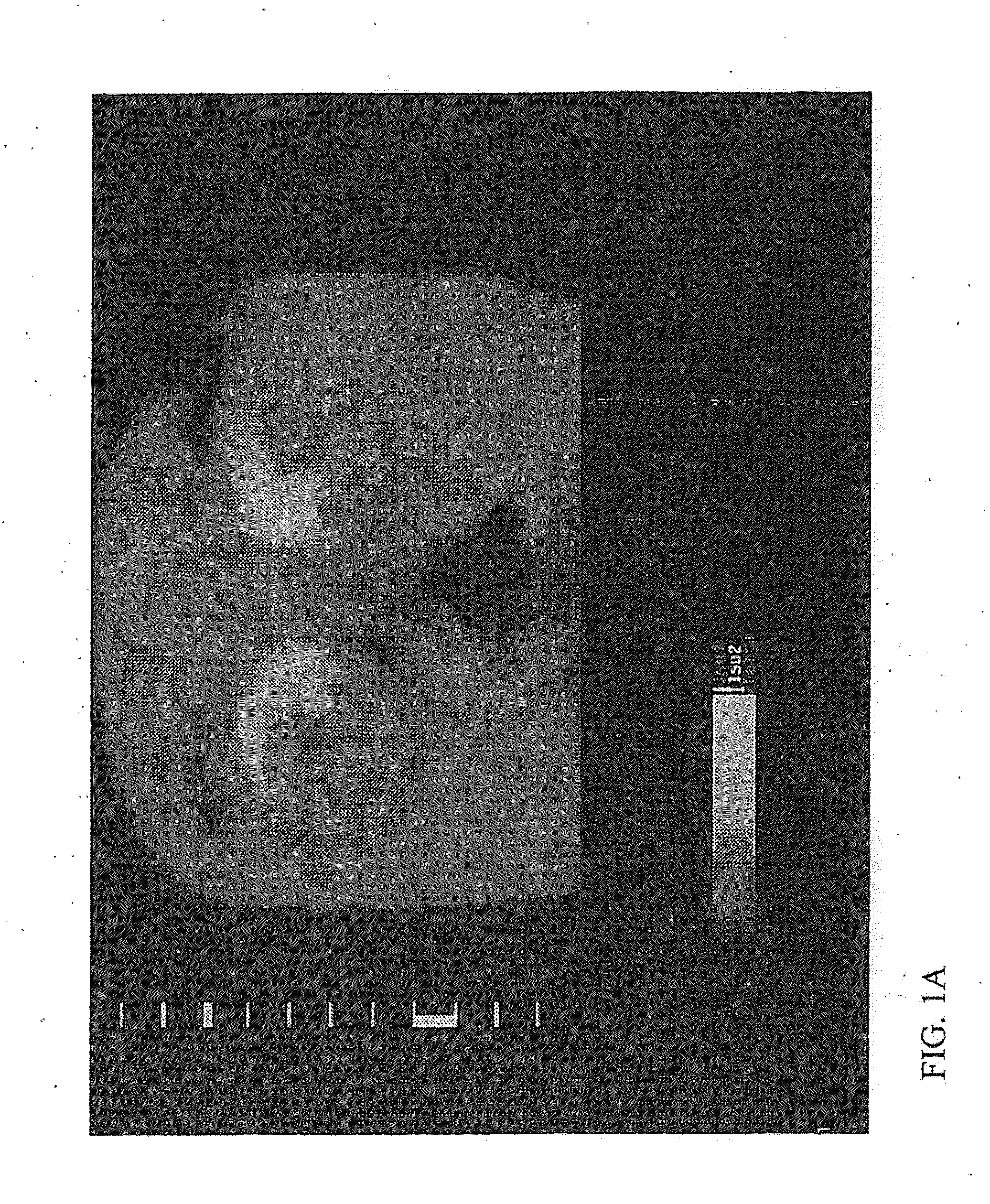
[0268]FIG. 1A shows a thermal infrared image of the human face showing a physiologic tunnel. The figure shows an image of the end of the brain temperature tunnel (BTT) depicted as white bright spots in the medial canthal area and the medial half of the upper eyelid. The end of the BTT on the skin has special geometry, borders, and internal areas and the main entry point is located on the supero-medial aspect of the medial canthal area diametrically in position with the inferior portion of the upper eyelid and 4 mm medial to the medial corner of the eye. From there the boundary goes down in the m...


PUM


Abstract

Support structures for positioning sensors on a physiologic tunnel for measuring physical, chemical and biological parameters of the body and to produce an action according to the measured value of the parameters. The support structure includes a sensor fitted on the support structures using a special geometry for acquiring continuous and undisturbed data on the physiology of the body. Signals are transmitted to a remote station by wireless transmission such as by electromagnetic waves, radio waves, infrared, sound and the like or by being reported locally by audio or visual transmission. The physical and chemical parameters include brain function, metabolic function, hydrodynamic function, hydration status, levels of chemical compounds in the blood, and the like. The support structure includes patches, clips, eyeglasses, head mounted gear and the like, containing passive or active sensors positioned at the end of the tunnel with sensing systems positioned on and accessing a physiologic tunnel.

Description

[0001]This application is a continuation of U.S. Ser. No. 10 / 786,623, filed Feb. 26, 2004, herein incorporated in its entirety by reference.FIELD OF THE INVENTION[0002]The present invention includes support and sensing structures positioned in a physiologic tunnel for measuring bodily functions and to manage abnormal conditions indicated by the measurements.BACKGROUND OF THE INVENTION[0003]Interfering constituents and variables can introduce significant source of errors that prevent measured biologic parameters from being of clinical value. In order to bypass said interfering constituents and achieve undisturbed signals, invasive and semi-invasive techniques have been used. Such techniques have many drawbacks including difficulties in providing continuous monitoring for long periods of time. Non-invasive techniques also failed to deliver the clinical usefulness needed. The placement of a sensor on the skin characterized by the presence of interfering constituents do not allow obtain...

Claims


Application Information

Patent Timeline
Patent Type & Authority Applications(United States)
IPC IPC(8): A61B5/01A61B5/00
CPCA61B5/01A61B5/0075A61B5/7405A61B5/746A61B5/0008A61B5/14532A61B5/14546A61B5/14553A61B5/4064A61B5/412A61B5/6803A61B5/6821A61B2562/02A61B5/021A61B5/02416
Inventor ABREU, MARCIO MARC
Owner BRAIN TUNNELGENIX TECH CORP
Learn More