
Multi-parameter high gradient magnetic separator and methods of use thereof

Inactive Publication Date: 2015-06-04
BIOMAGNETIC SOLUTIONS LLC
View PDF3 Cites 10 Cited by
  • Summary
  • Abstract
  • Description
  • Claims
  • Application Information

AI Technical Summary

Benefits of technology

The patent describes a separation device that can create strong magnetic gradients, allowing for effective separation of target entities. This device can handle viscous and complex media and can perform other operations on the captured entities. The use of less magnetic labeling material reduces costs and avoids unwanted materials.

Problems solved by technology

Unfortunately, prior art devices of this kind do not readily lend themselves to separations of large volumes or to separations involving viscous media, where the intent is to recover the magnetic entities particularly of biological entities such as cells, bacteria and the like.
Retrieval of captured entities of interest is not an easy or efficient task.
Accordingly, positive selections (where the item of interest is magnetically captured and subsequently recovered) are very difficult to accomplish with the Miltenyi systems.
The internal gradient device of Liberti '084, although designed for positive selections, is limited with regard to the sample size that can be processed.
In addition, the device is cumbersome and would be difficult to automate.

Method used


Image

  • Multi-parameter high gradient magnetic separator and methods of use thereof
  • Multi-parameter high gradient magnetic separator and methods of use thereof
  • Multi-parameter high gradient magnetic separator and methods of use thereof

Examples


example 1

Construction of Simple Prototype, FF Removal and T Cell Capture

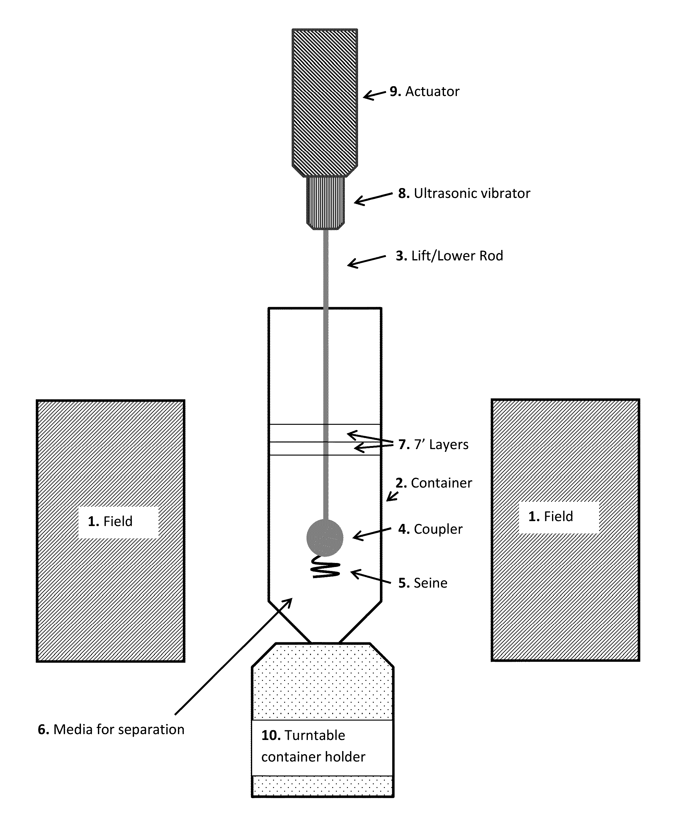
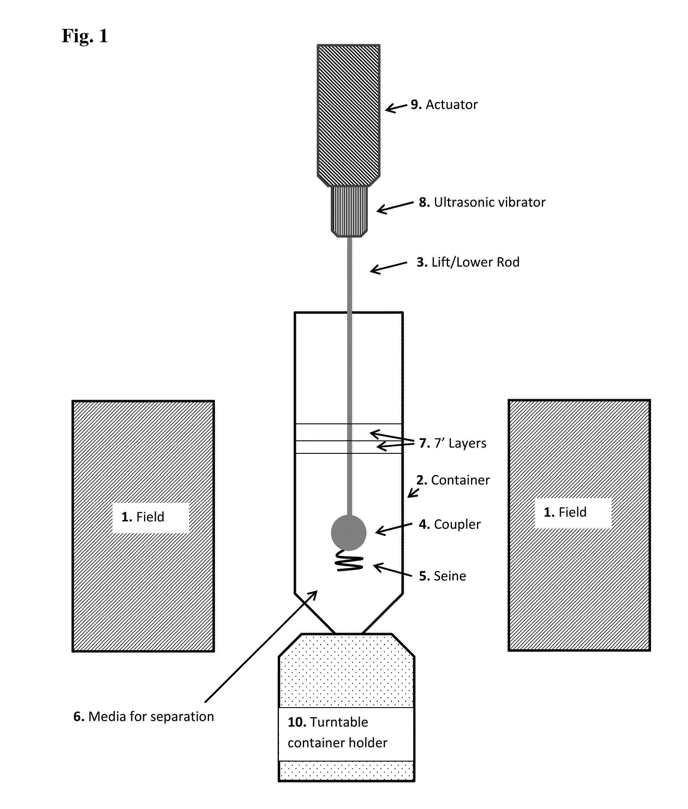
[0064]A sufficiently uniform magnetic field for inducing magnetic gradients on Seines was created by constructing dipole magnet from a “U” shaped yoke having soft steel sides of 4.0×4.5×0.5″ and a back plate that held the sides apart by 2.0″, wherein 3.0×2.5 by 0.5 inch block magnets (magnetized through the 0.5″ dimension) were affixed to the inside walls of the yoke in a North-South orientation, and separated by a gap distance of 1.0″. This arrangement creates a gap volume of 3×2.5×1″. 3.0×0.5×0.4 inch magnets (magnetized through the 0.4″ dimension) were placed adjacent to and in the same orientation on both vertical sides of the large block magnets in order to keep the field lines resulting from the magnetic circuit of the large block magnets from bulging out (and creating gradients); thus creating a substantial volume between the large block magnets where a ferromagnetic object could be moved into, out of and within t...

example 2

Preparation of Sienes Barrier Coatings that Modify Effective Induced Magnetic Gradients

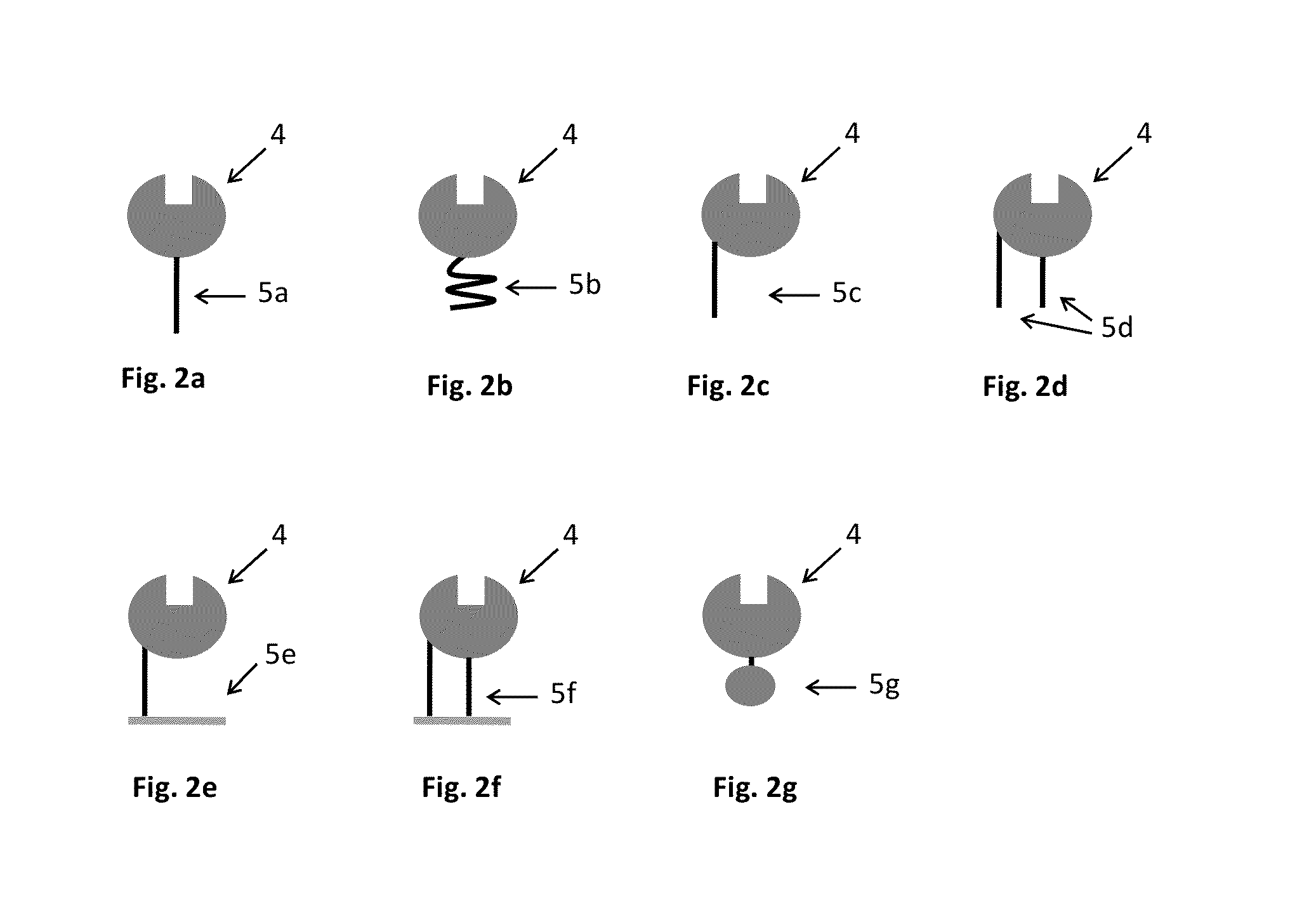
[0068]There are instances where it is desirable to coat ferromagnetic rods used in constructing Seines just for the purpose of affording easy release of magnetically collected entities and materials for doing that have been cited. Alternatively where it is desirable to modulate the gradient of a Seine of some particular diameter Ferromagnetic rods, e.g. iron, nickel, used to create Sienes, such rods or structures can be encapsulated with micro-tubing that is nontoxic, non-pyrogenic and biocompatible, thereby in a virtual manner effectively increasing the diameter of the rod and thus lowering the gradient that captured entities experience at the Seine surface. This can readily be done with commercially available tubes (i.e. microprobe tubing) that is stiff enough for easy handling and soft enough to resist puncturing. The inner diameter of such tubes can be as small as 1 mm, or be made smaller by s...


PUM


Abstract

Disclosed is a high gradient magnetic separation apparatus for recovering magnetic ally labeled target entities from viscous and / or complex test media. The target entities are captured on a ferromagnetic element in which a magnetic field gradient is induced by a magnetic field source. The apparatus is designed to perform various operations on captured target entities. Methods of using the apparatus are also disclosed, e.g., for isolation of circulating tumor cells.

Description

CROSS-REFERENCE TO RELATED APPLICATIONS[0001]The present application claims the benefit of U.S. Provisional Patent Application No. 61 / 911,163, filed Dec. 3, 2013, the entire disclosure of which is incorporated by reference herein.BACKGROUND OF THE INVENTION[0002]Various laboratory and clinical procedures employ bio-specific affinity reactions. Such reactions are commonly used in diagnostic testing of biological samples, or for the separation or enrichment of a wide range of target substances, especially biological entities such as cells, proteins, nucleic acid sequences, and the like.[0003]In addition to using some physical property of a target entity (e.g. size, charge, and density), various methods are available for analyzing or separating the above-mentioned target substances based upon complex formation between the substance of interest and one or more other substance to which the target substance specifically binds. Separation of complexes from unbound material may be accomplis...

Claims


Application Information

Patent Timeline
IPC IPC(8): G01N1/44G01N1/04
CPCG01N1/04G01N1/44G01N35/0098G01N2035/0439B03C1/01B03C1/0332B03C1/0335B03C1/286B03C1/288B03C1/30B03C2201/18B03C2201/26
Inventor LIBERTI, PAUL A.STEPHENS, JASON R.KHRISTOV, TODOR R.LIBERTI, THEODORE L.
Owner BIOMAGNETIC SOLUTIONS LLC
Learn More