Apparatus for reducing the effect of contamination on a rapid thermal process

a technology of thermal process and apparatus, which is applied in the direction of instruments, semiconductor/solid-state device testing/measurement, furnaces, etc., can solve the problems of affecting the processing temperature, affecting the crystallinity, and the dopant will not come to rest, so as to improve the cost-of-ownership of the process, reduce the downtime of the chamber, and improve the temperature uniform effect of processing

Active Publication Date: 2015-06-04
APPLIED MATERIALS INC
View PDF7 Cites 17 Cited by
  • Summary
  • Abstract
  • Description
  • Claims
  • Application Information

AI Technical Summary

Benefits of technology

[0015]Embodiments of the present disclosure provide a cover assembly that includes a cover that is disposed between a device side surface of a substrate and a reflector plate, which are disposed within a thermal processing chamber. The presence of the cover between the device side surface of a substrate and a reflector plate has many advantages over conventional thermal processing chamber designs, which include improved temperature uniformity during processing, reduced chamber down time and improved cost-of-ownership of the processes performed in the thermal processing chamber.

Problems solved by technology

Ion implantation of chemical impurities disrupts the crystallinity of the semiconductor substrate over the range of the implant.
However, the implanted dopants will not come to rest on electrically active sites in the substrate.
This deposition created by the outgassing process interferes with the temperature pyrometer readings and with the radiation distribution fields on the substrate, which in turn affects the processing temperature at which the substrate is annealed.
Deposition of the outgassed impurities may also cause unwanted particles to deposit on the substrate and may also generate slip lines on the substrate.
The wet clean process requires manual intervention to clean the deposited material from the chamber walls and from the reflector plate, which may be labor intensive requiring the chamber to be offline for about four hours.

Method used


Image

  • Apparatus for reducing the effect of contamination on a rapid thermal process
  • Apparatus for reducing the effect of contamination on a rapid thermal process
  • Apparatus for reducing the effect of contamination on a rapid thermal process

Examples


Embodiment Construction

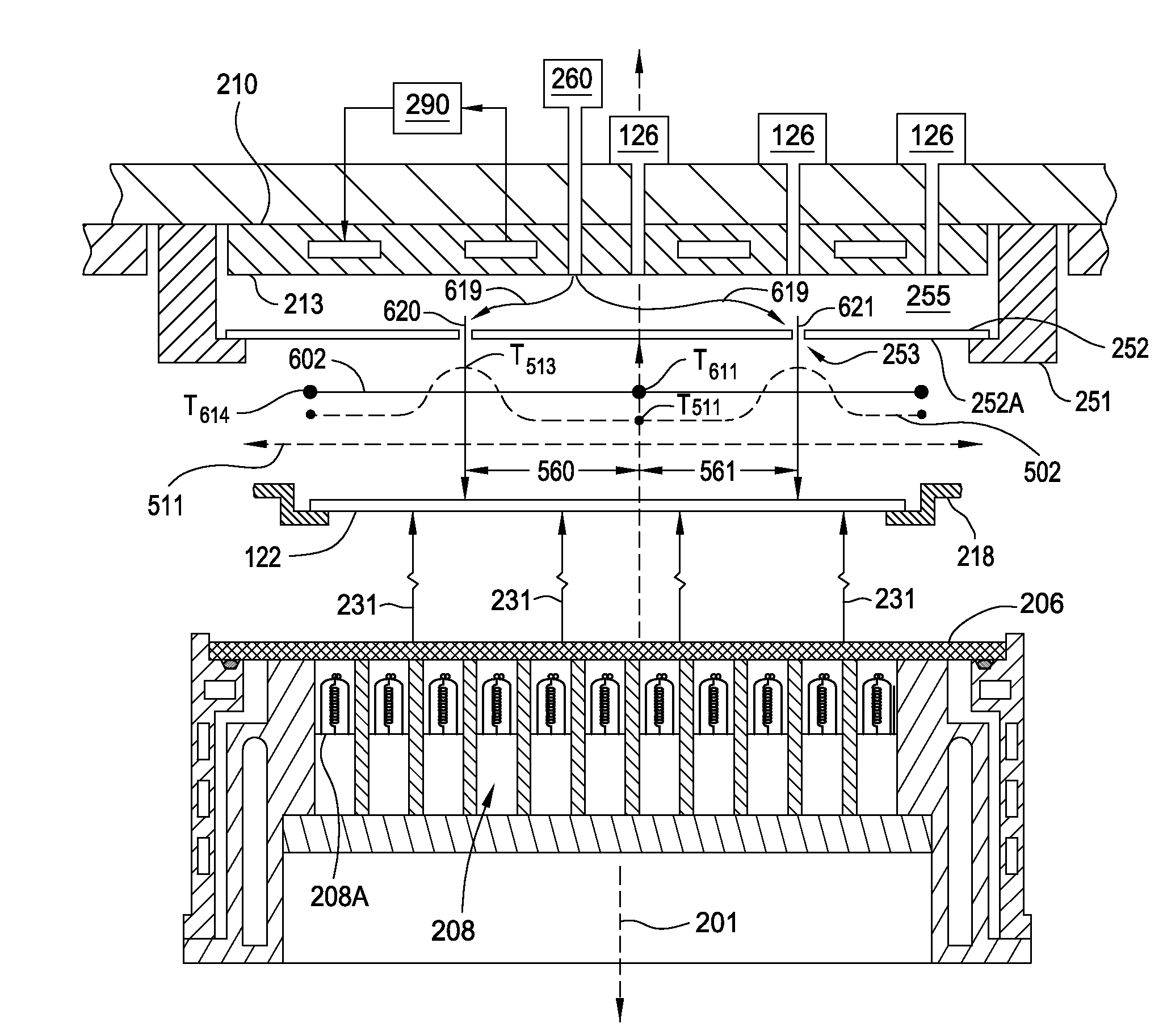
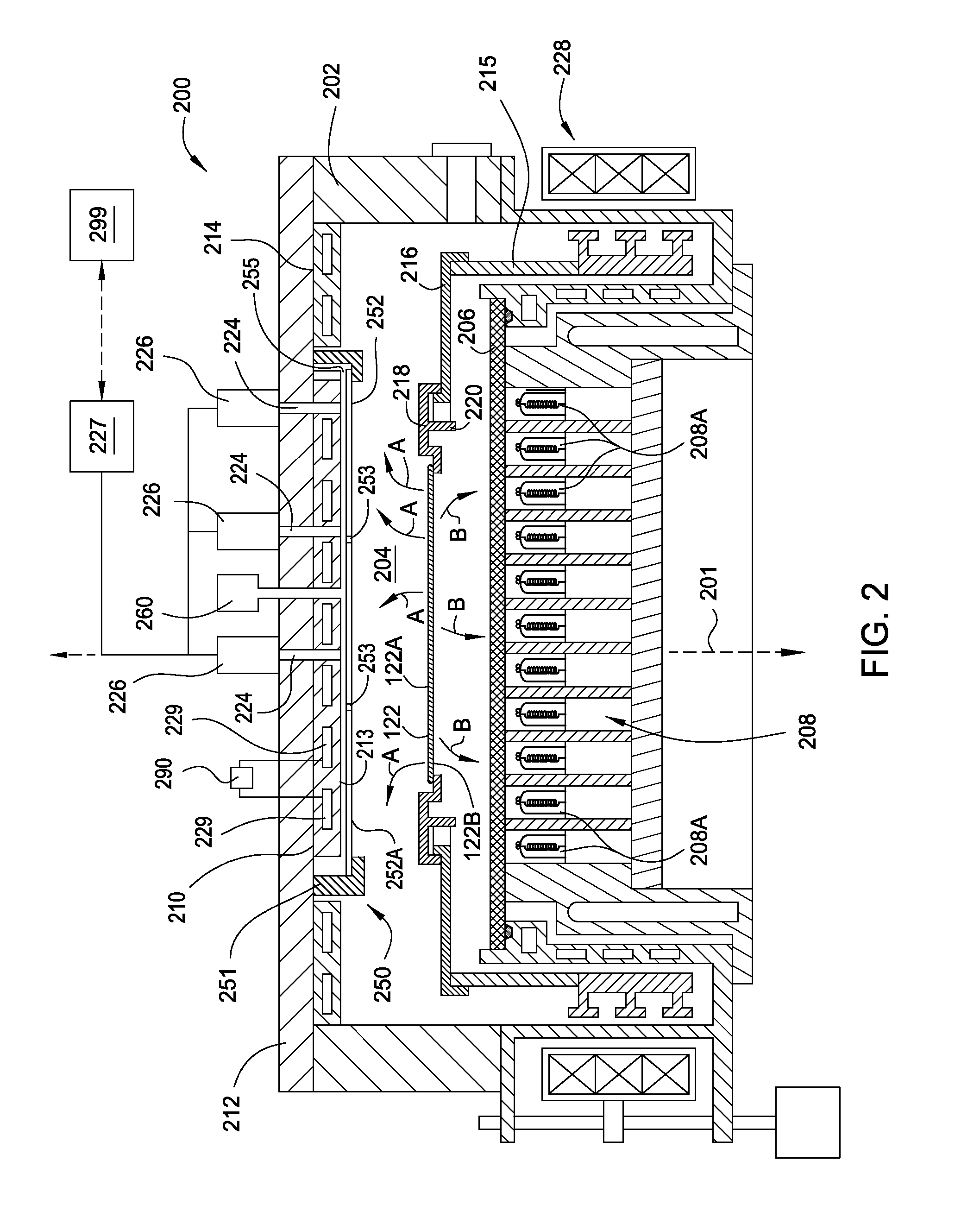
[0026]Embodiments of the present disclosure provide apparatus and methods for fabricating devices on a substrate. More particularly, embodiments of the present invention provide an apparatus that is configured to provide improved thermal processing uniformity, reduce the cost of consumable parts created during processing and have a reduced chamber downtime due to the need to complete cleaning operation after a number of substrates have been processed in the processing chamber.

[0027]Embodiments of the present disclosure provide a cover assembly that includes a cover that is disposed between a device side surface of a substrate and a reflector plate, which are all disposed within a thermal processing chamber. In some configurations, the cover includes two or more ports that are formed therein and are positioned to deliver a gas, from a space formed between the reflector plate and the cover, to desired regions of the substrate during processing to reduce the temperature variation acros...


PUM


Abstract

Embodiments of the present disclosure provide a cover assembly that includes a cover disposed between a device side surface of a substrate and a reflector plate, which are disposed within a thermal processing chamber. The presence of the cover between the device side surface of a substrate and a reflector plate has many advantages over conventional thermal processing chamber designs, which include an improved temperature uniformity during processing, a reduced chamber down time and an improved cost-of-ownership of the processes performed in the thermal processing chamber. In some configurations, the cover includes two or more ports that are formed therein and are positioned to deliver a gas, from a space formed between the reflector plate and the cover, to desired regions of the substrate during processing to reduce the temperature variation across the substrate.

Description

CROSS-REFERENCE TO RELATED APPLICATIONS[0001]This application claims benefit of U. S. provisional patent application Ser. No. 61 / 909,310, filed Nov. 26, 2013, which is hereby incorporated herein by reference.BACKGROUND[0002]1. Field[0003]Embodiments of the present disclosure generally relate to methods and apparatus for thermally processing a substrate.[0004]2. Description of the Related Art[0005]Substrate processing systems are used to fabricate semiconductor logic and memory devices, flat panel displays, CD ROMs, and other devices. During processing, such substrates may be subjected to chemical vapor deposition (CVD) and rapid thermal processes (RTP); RTP processes include, for example, rapid thermal annealing (RTA), rapid thermal cleaning (RTC), rapid thermal CVD (RTCVD), rapid thermal oxidation (RTO), and rapid thermal nitridation (RTN). RTP systems usually include a heating lamps which radiatively heat the substrate through a light-transmissive window. RTP systems may also incl...

Claims


Application Information

Patent Timeline
Patent Type & Authority Applications(United States)
IPC IPC(8): H01L21/67H01L21/66H01L21/324
CPCH01L21/67115H01L21/67248H01L22/10H01L21/324H01L21/68792H01L21/02H01L21/3242
Inventor MILLER, AARONBEHDJAT, MEHRANTAM, NORMAN L.LIU, MICHAEL
Owner APPLIED MATERIALS INC
Why Eureka
Try Eureka